
Power management system for use in laptop computer and management method thereof

a technology for managing systems and laptop computers, applied in computing, power supply for data processing, instruments, etc., can solve problems such as reducing the possibility of mass production in a short time for time-to-market product development, serious incompatibility with the power design of related components in existing laptop computers, etc., to avoid the impact of unnecessary leakage current, avoid damage to circuits and components easily

Active Publication Date: 2008-02-07
VIDEOLABS
View PDF5 Cites 4 Cited by
  • Summary
  • Abstract
  • Description
  • Claims
  • Application Information

AI Technical Summary

Benefits of technology

[0005]Therefore, it is a primary object of the present invention to overcome the shortcomings of a prior art battery with a fixed quantity of electric power by providing a lightweight and convenient pluggable external power apparatus for supplying more power to a laptop computer. Therefore, a fuel battery or a solar energy battery becomes a solution for the aforementioned problem.
[0006]However, further improvements are needed for the fuel battery or solar energy battery to generate the same quantity of electric power as those generated by a lithium battery. If we want to use a battery together with an external power apparatus for supplying power alternately to achieve the required power requirement, then it is necessary to make substantial modifications to the power circuit of the laptop computers, and such modifications may easily cause a serious incompatibility issue to the power design of related components in existing laptop computers. Furthermore, such large modification to the circuit design of the laptop computers requires a series of tests and certifications, and thus reducing the possibility of achieving a mass production in a short time for a time-to-market product development.
[0007]In view of the foregoing shortcomings, the present invention provides an external power apparatus capable of directly supplying a DC voltage such as 5 volts, 3.3 volts, 2.5 volts or 1.8 volts to a subsystem in a laptop computer. If a small power fuel battery or solar energy battery is included into the external power apparatus and connected in parallel with the DC power subsystem for supplying electric power, then the power supply of the battery installed in the laptop computer can be shared. In addition, the required DC voltage of the subsystem is constant, and thus such parallel connection method is much simpler than the aforementioned circuit design for the mixed power supply. In other words, the present invention can avoid substantial modifications to the circuit design and overcome the time-to-market problem.
[0009]The invention avoids the external power apparatus from supplying power when the laptop computer is turned off, which may cause damages to circuits and components easily.
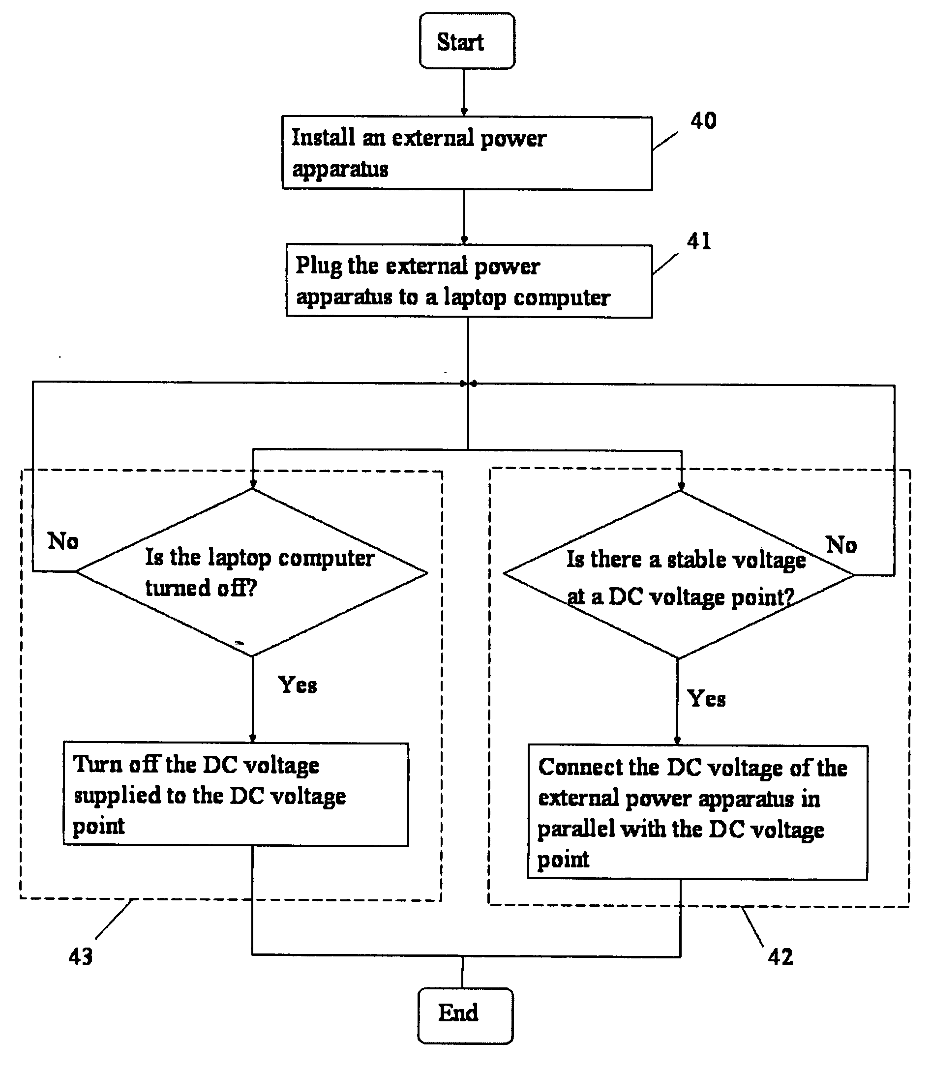
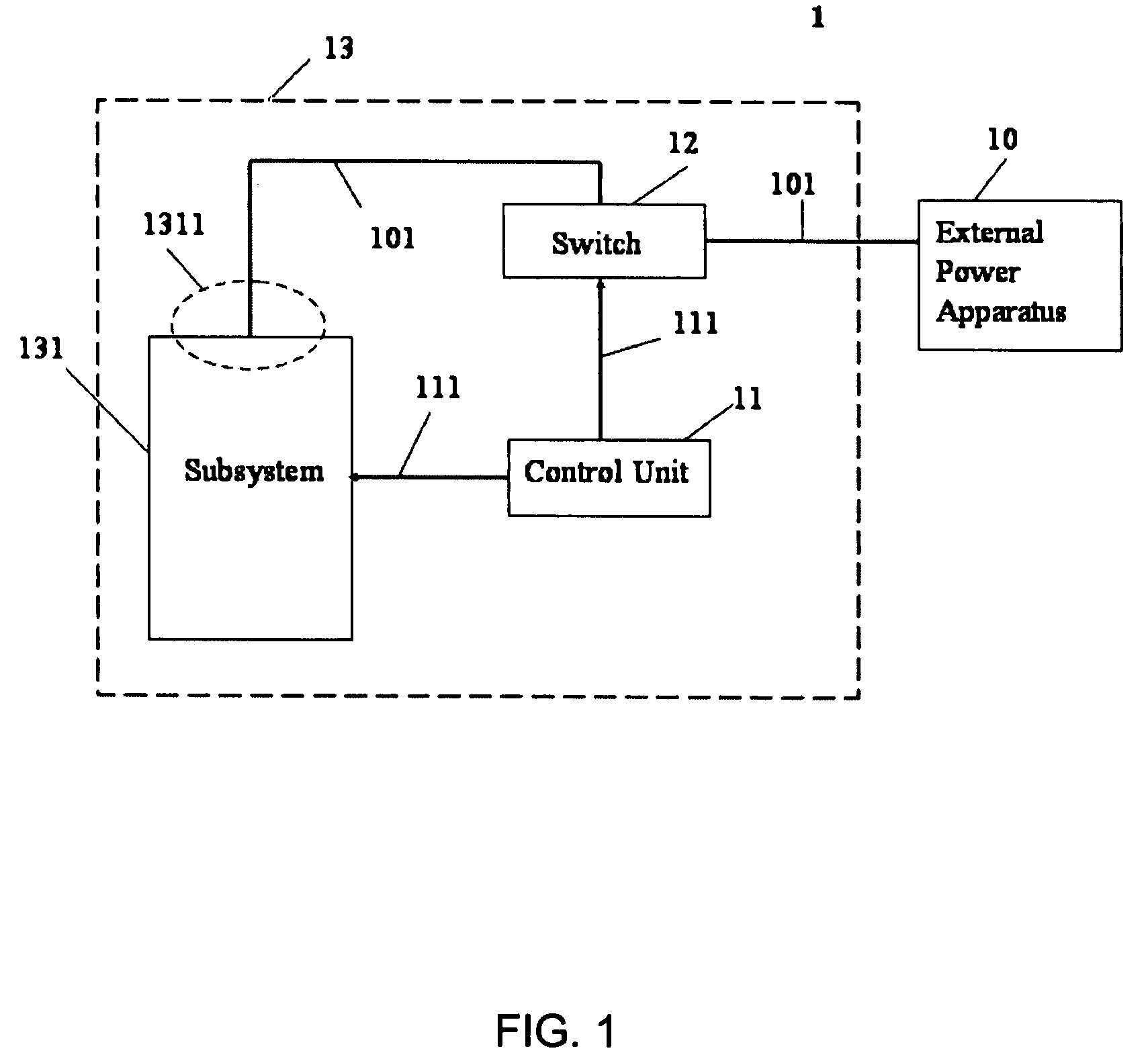
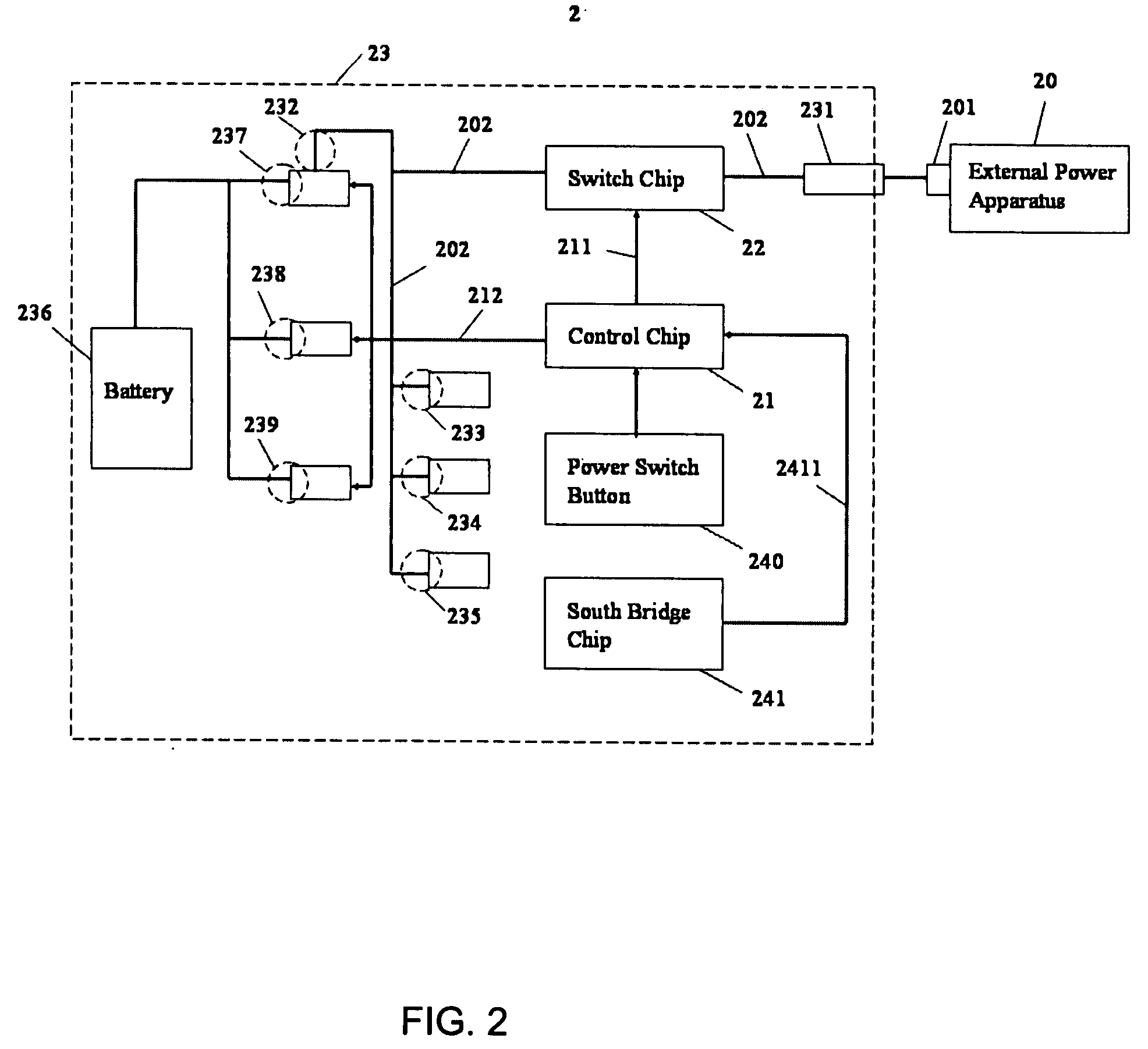
[0010]Another object of the present invention is to install a control unit and a switch on a laptop computer for turning on / off the power of the external power apparatus and protecting a subsystem circuit in the laptop computer, so as to avoid the impact of unnecessary leakage currents. In other words, if the laptop computer is turned on and the DC voltage at the DC voltage point in the subsystem becomes stable (such as 5 volts), the control unit will send a control signal to a switch, such that the DC voltage of the external power apparatus can be supplied to the laptop computer for a power supply. If the laptop computer is turned off, the control unit will send another control signal to the switch to turn off the external power apparatus and stop supplying a DC voltage to the laptop computer for the power supply.

Problems solved by technology

If we want to use a battery together with an external power apparatus for supplying power alternately to achieve the required power requirement, then it is necessary to make substantial modifications to the power circuit of the laptop computers, and such modifications may easily cause a serious incompatibility issue to the power design of related components in existing laptop computers.
Furthermore, such large modification to the circuit design of the laptop computers requires a series of tests and certifications, and thus reducing the possibility of achieving a mass production in a short time for a time-to-market product development.

Method used


Image

  • Power management system for use in laptop computer and management method thereof
  • Power management system for use in laptop computer and management method thereof
  • Power management system for use in laptop computer and management method thereof

Examples


Embodiment Construction

[0016]The above and other objects, features and advantages of the present invention will become apparent from the following detailed description of preferred embodiments taken with the accompanying drawings, and same numerals are used to indicate same elements for the illustration of the invention.

[0017]Referring to FIG. 1 for a schematic block diagram of a power management system of a laptop computer in accordance with the present invention, the power management system 1 comprises an external power apparatus 10, a control unit 11 and a switch 12. The control unit 11 and the switch 12 can be disposed in the laptop computer 13 and connected to a subsystem 131 in the laptop computer 13. In this embodiment, the external power apparatus 10 can be installed to the laptop computer 13 through an interface such as a USB interface, a PCMCIA interface or a card interface for providing a pluggable function to the external power apparatus 10 and supplying a DC voltage 101 to the laptop computer...


PUM


Abstract

A power management system for use in a laptop computer and a power management method are disclosed. The power management system includes an external power apparatus and a control unit and a switch disposed in the laptop computer. The external power apparatus is pluggable and supplies direct current (DC) between 5 and 1.8 DC voltages to the laptop computer. The switch can turn on / off the direct current to at least one DC voltage point within the laptop computer based on a control signal sent from the control unit.

Description

FIELD OF THE INVENTION[0001]The present invention relates to a power management system for use in a laptop computer and a management method thereof, and more particularly to a technical area that controls an external power apparatus.BACKGROUND OF THE INVENTION[0002]At present, a certain level of advancement and result is achieved in the area of power management for a battery of a laptop computer, but the extended using time of the battery operated in a battery with a fixed quantity of power is very limited, even though good power management methods are provided for hardware components, software operating systems or driver programs.[0003]There are different power management methods, and most of them allow the components temporarily not in use to enter a power saving mode or a sleep mode to save the power consumption of a battery. These methods that adopt a power saving mode or a sleep mode are nothing more than focusing on voltage or frequency, but the functions of present laptop com...

Claims


Application Information

Patent Timeline
Patent Type & Authority Applications(United States)
IPC IPC(8): G06F1/00
CPCG06F1/263
Inventor JUAN, KUAN-CHI
Owner VIDEOLABS
Learn More