Inertial sensor, inertial sensor device and manufacturing method the same

a technology of inertial sensor and manufacturing method, which is applied in the direction of turn-sensitive devices, acceleration measurement using interia forces, instruments, etc., can solve the problems of deteriorating detection performance, insufficient software arithmetic processing, and insufficient detection performance, so as to improve workability and avoid deteriorating detection performance of detection elements. , the effect of accurately setting the detection axis of the sensor

Inactive Publication Date: 2008-02-14
COLUMBIA PEAK VENTURES LLC
View PDF6 Cites 15 Cited by
  • Summary
  • Abstract
  • Description
  • Claims
  • Application Information

AI Technical Summary

Benefits of technology

[0023]An advantage of the invention is to provide an inertial sensor that can set a detection axis at a predetermined angle without deteriorating detection performance of a detection element.
[0024]Another advantage of the invention is to provide a method for manufacturing an inertial sensor device that can accurately set the detection axis of the sensor when the device is fixed on a mount surface having a predetermined tilt angle, and can set a predetermined angle that the detection axis of the sensor makes with respect to a bottom surface and an upper surface of a molded package, improving workability.
[0025]An inertial sensor according to a first aspect of the invention includes a detection element detecting an amount of a physical quantity in a detection axis direction, a plurality of support members having flexibility and supporting nearly a center of the detection element, and a package substrate housing the detection element and the plurality of support members. In a case when an X-axis is defined as an extending direction of the plurality of support members, a Y-axis is perpendicular to the X-axis in a plane including the detection element, and a Z-axis is perpendicular to the X-axis and the Y-axis, one of load components in a direction of the Y-axis of the detection member applied to the plurality of support members is nearly equal to other among the plurality of support members, and one of load components in a direction of the Z-axis is nearly equal to the other among the plurality of support members.
[0026]This structure can render the setting condition of mechanical resonance frequency of each support member robust to the change of force caused by acceleration since an effect due to the acceleration is equally applied to each support member. That is, the following trouble can be prevented. The resonance frequency of the support member varies to an unexpected value. In addition, the resulting frequency approaches near the driven vibration of the inertial sensor during a process in which the driven frequency of the inertial sensor varies with a temperature change. The driven vibration frequency of the inertial sensor is coupled with (attracted to) the resonance frequency of the support member. As a result, the output signal of the inertial sensor jumps.
[0027]In this case, the detection element may have a detection axis that detects an angular velocity and coincides with the direction of the Z-axis that makes an angle of θ with respect to a vertical direction, and a resulting load combined by the component in the direction of the Y-axis of the load and the component in the direction of the Z-axis of the load may be at least a load component based on gravity acceleration.
[0028]This structure can render the setting condition of mechanical resonance frequency of each support member robust to the change of force caused by acceleration since an effect due to the acceleration is equally applied to each support member even when the inertial sensor is set tilted. That is, the following trouble can be prevented. The resonance frequency of the support member varies to an unexpected value. In addition, the resulting frequency approaches near the driven vibration of the inertial sensor during a process in which the driven frequency of the inertial sensor varies with a temperature change. The driven vibration frequency of the inertial sensor is coupled with (attracted to) the resonance frequency of the support member. As a result, the output signal of the inertial sensor jumps.

Problems solved by technology

The software arithmetic processing, however, is insufficient.
The sensors disclosed in the first and second examples, however, may deteriorate detection performance due to acoustic leakages or unwanted vibration modes of the quartz crystal resonator yielded from a fixture since the quartz crystal resonator serving as a detection element is directly fixed to the fixture.
As a result, production costs soar.
This process causes a high cost of a detection element, increasing total production costs.
Furthermore, in the first and second examples the angle of a detection axis cannot be set to any angle when a sensor is mounted on a mount board since a detection element is set tilted within a sensor.
Further, a support (bonding wire) connecting a vibrating element (vibrator) to a support substrate shown in the third example significantly affects occurrence of acoustic leakages and unwanted vibration modes from the vibrating element, sometimes deteriorating detection performance of the sensor.
In addition, changing the angle with using the adhesive causes large variations in production, resulting in a setting angle being inaccurate.
Further directly fixing an element to a fixture in the first and second examples also causes occurrence of acoustic leakages and unwanted vibration modes from the vibrating element, resulting in a setting angle being inaccurate.
This outline may worsen workability in mounting processes.

Method used


Image

  • Inertial sensor, inertial sensor device and manufacturing method the same
  • Inertial sensor, inertial sensor device and manufacturing method the same
  • Inertial sensor, inertial sensor device and manufacturing method the same

Examples


first embodiment

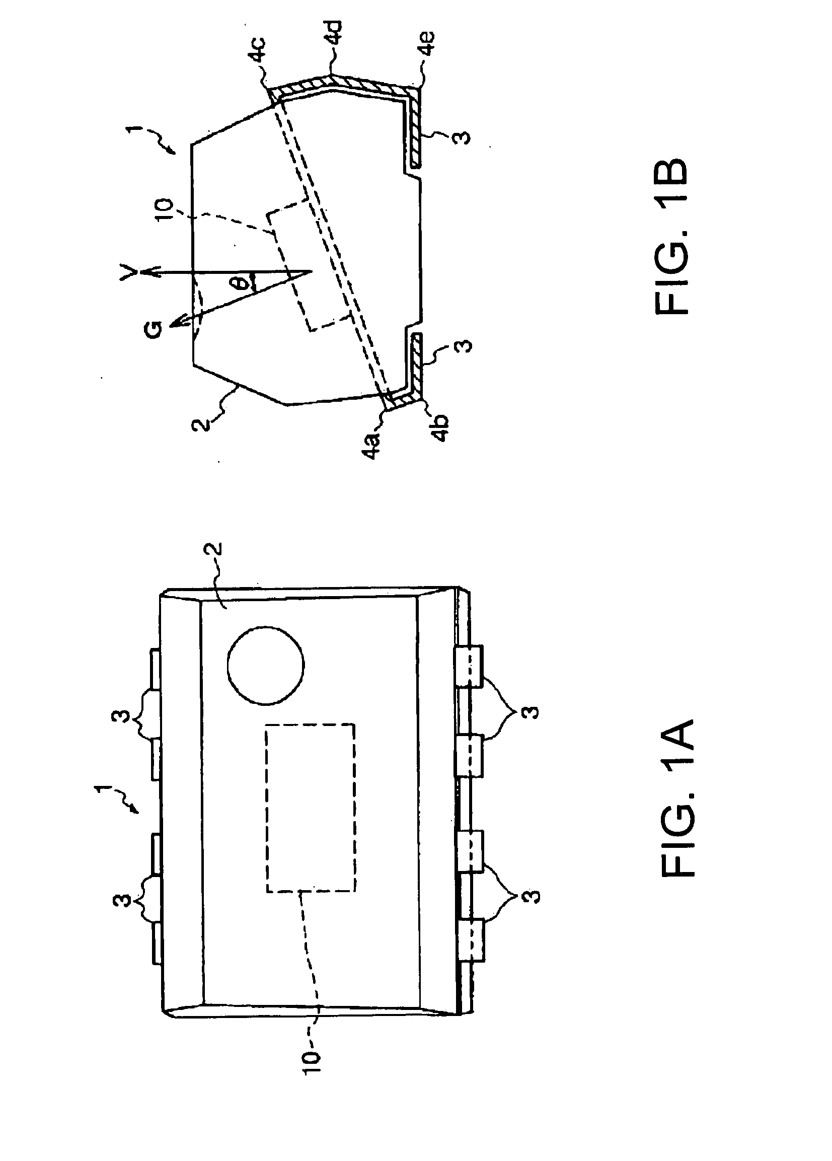
[0070]FIGS. 1A and 1B are schematic views illustrating the structure of a gyro sensor device of the invention. FIG. 1A is the top view. FIG. 1B is the side view.

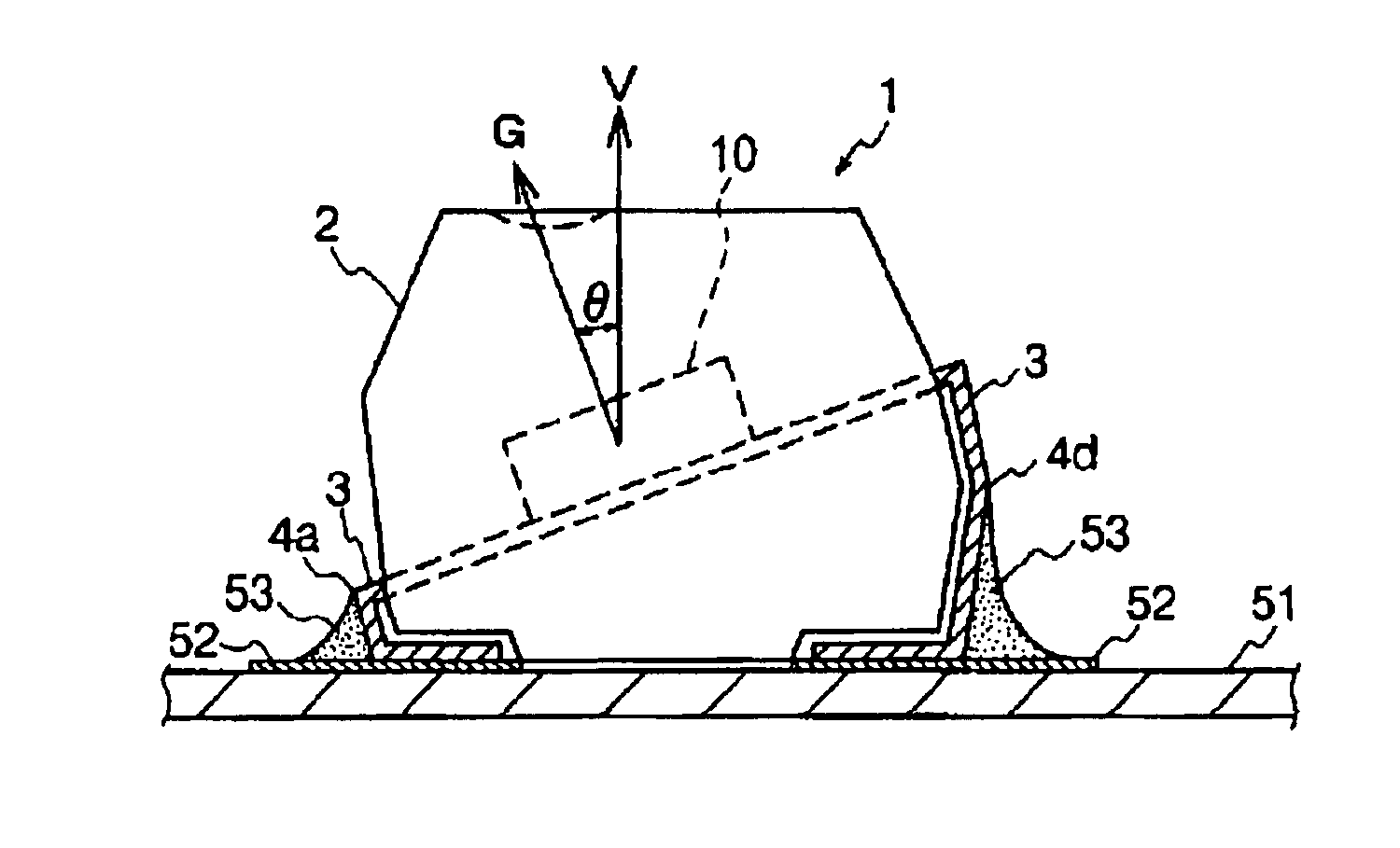
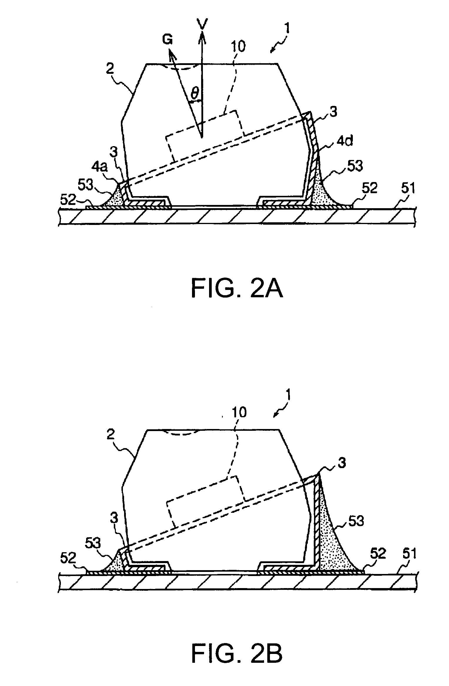
[0071]In a gyro sensor device 1 shown in FIGS. 1A and 1B, a gyro sensor 10 is sealed with a resin part 2, formed by a molding compound such as resin, so that the angular velocity detection axis G (detection axis G) of the gyro sensor 10 is tilted by an angle θ with respect to the perpendicular line V of the upper surface of the gyro sensor device 1. From both the long sides of the resin part 2, a plurality of lead terminals extends outside.

[0072]Here, the upper surface and a mounting side surface (the other surface opposite to the upper surface) of the gyro sensor device 1 are in parallel with each other. The lead terminals 3 are electrically connected to the gyro sensor 10 inside the resin part 2. The lead terminals 3 exposed from the resin part 2 at a position close to its bottom surface are bent inside at bending parts 4a...

second embodiment

[0120]FIG. 5 is a schematic view illustrating the structure of a gyro sensor device according to the invention.

[0121]In a gyro sensor device 20 shown in FIG. 5, the gyro sensor 10 is sealed with the resin part 2 so that the detection axis G of the gyro sensor 10 is tilted by the angle θ with respect to the perpendicular line of a mount surface on which the gyro sensor device 20 is mounted.

[0122]In this case, also, the lead terminal 3 extends outside from both the long sides of the resin part 2 in a plurality of numbers. The gyro sensor 10 is tilted by the angle θ with respect to the upper surface of the gyro sensor device 1 by supporting with the lead terminal 3, bent at the bending parts 6e, 6f, and 6g in the resin part 2. In the structure, the length between the bending parts 6a and 6b is nearly equal to the length between the bending parts 6c and 6d. This structure can prevent the occurrence of errors in the tilt angle of the gyro sensor device 20 when it is mounted to the mount ...

third embodiment

[0128]FIG. 7 is a schematic view illustrating the structure of a gyro sensor device according to the invention.

[0129]In a gyro sensor device 30 shown in FIG. 7, the gyro sensor 10 is sealed with the resin part 2 so that the gyro sensor 10 is tilted by the angle θ with respect to the vertical direction of a mount surface on which the gyro sensor device 30 is mounted.

[0130]In this case, also, the lead terminal 3 extends outside from both the long sides of the resin part 2 in a plurality of numbers. The gyro sensor 10 is tilted by the angle θ with respect to the upper surface of the gyro sensor device 30 by supporting with the lead terminal 3, bent in a step shape at the bending parts 7e, 7f, 7g, 7h, 7i, 7j, 7k and 7l in the resin part 2. In the structure, the length between the bending parts 7a and 7b is nearly equal to the length between the bending parts 7c and 7d. This structure can prevent the occurrence of errors in the tilt angle of the gyro sensor device 30 when it is mounted t...


PUM

PropertyMeasurementUnit
tilt angleaaaaaaaaaa
physical quantityaaaaaaaaaa
flexibilityaaaaaaaaaa

Abstract

An inertial sensor, comprises a detection element detecting an amount of a physical quantity in a detection axis direction, a plurality of support members having flexibility and supporting nearly a center of the detection element, and a package substrate housing the detection element and the plurality of support members. In a case when an X-axis is defined as an extending direction of the plurality of support members, a Y-axis is perpendicular to the X-axis in a plane including the detection element, and a Z-axis is perpendicular to the X-axis and the Y-axis, one of load components in a direction of the Y-axis of the detection member applied to the plurality of support members is nearly equal to other among the plurality of support members, and one of load components in a direction of the Z-axis is nearly equal to the other among the plurality of support members.

Description

BACKGROUND[0001]1. Technical Field[0002]The present invention relates to an inertial sensor such as an acceleration sensor and a gyro sensor and a method for manufacturing it, and is particularly preferred for in-vehicle navigation devices.[0003]2. Related Art[0004]In-car navigation devices are popularly spread out. When detecting a current position of a vehicle via such device, two methods are combined: a method for positioning a vehicle by using a so-called global positioning system (GPS), and a method for autonomously positioning the moving direction and distance of a vehicle. In order to autonomously position the moving direction and distance of a vehicle, an inertial sensor such as a gyro sensor (an angular velocity sensor) for detecting acceleration or angular velocity yielded by a moving vehicle are mounted in car navigation devices.[0005]When acceleration or angular velocity is detected by using an inertial sensor, the detection axis of the sensor needs to be coincided with ...

Claims


Application Information

Patent Timeline
Patent Type & Authority Applications(United States)
IPC IPC(8): G01P3/00H01S4/00G01C19/56
CPCG01C19/56Y10T29/49002H05K3/3426G01P1/023H01L2924/181
Inventor MATSUNAGA, MASAYUKISATO, KENJI
Owner COLUMBIA PEAK VENTURES LLC
Why Eureka
Try Eureka