Multiaxial Universal Testing Machine

a universal testing machine and multi-axial technology, applied in the direction of instruments, force/torque/work measurement, tension measurement, etc., can solve the problems of hindering other testing configurations, no equipment capable of evaluating some behaviour parameters, etc., and achieve the effect of simplifying design and eliminating any slipping from the jaw

Inactive Publication Date: 2008-02-14
UNIVERSITY OF MINHO
View PDF2 Cites 35 Cited by
  • Summary
  • Abstract
  • Description
  • Claims
  • Application Information

AI Technical Summary

Benefits of technology

[0006]The rotational movement of the motor is converted into linear displacement of the jaw. The geared motor is responsible for low speed rotary motion and high torque, which is turned into linear displacement and force applied to the jaw. The main advantage of this mechanical solution is an overall axial alignment of the linear drive with the applied force, thus eliminating any undesirable bending moments. Furthermore the motor is equipped with a rotational encoder which gives the information to the electronic drive about the rotor position counting the number of rotations. With this information is possible to control accurately the rotor position and consequently the respective gripping jaw displacement.
[0008]The jaw is responsible for grabbing the test specimen by friction, therefore eliminating any slipping from the jaw. The gripping load is applied by a manually driven screw handle, therefore simplifying the design and eliminating any need for pneumatic pressure or complex and heavy electric actuators. In the interest of cleanliness, hydraulics has always been ruled out.

Problems solved by technology

Actually, there is no equipment capable to evaluate some behaviour parameters, like tensile, compression or fatigue, in different directions simultaneously.
Because the machine only has one axis, we only can perform uniaxial testing operations, which is the great disadvantage of this machine.
The particular disadvantage of this approach is the restriction imposed by the physical structure of the device, hindering others testing configurations for beyond the biaxial testing.

Method used


Image

  • Multiaxial Universal Testing Machine
  • Multiaxial Universal Testing Machine
  • Multiaxial Universal Testing Machine

Examples


Embodiment Construction

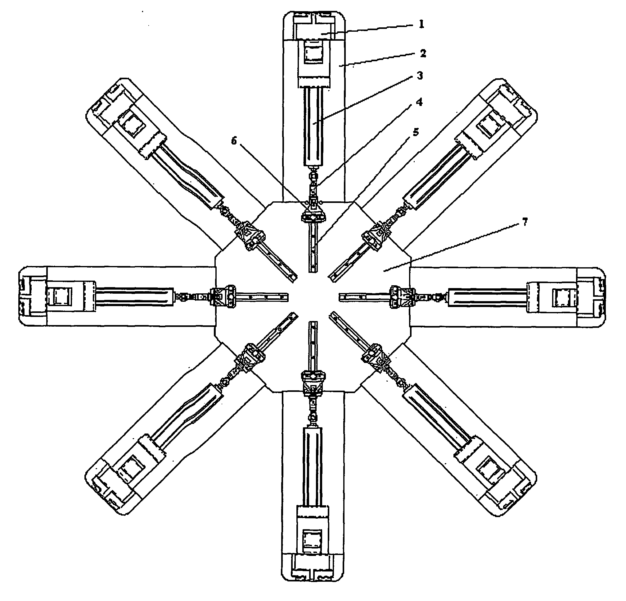
[0015]The testing machine shown in the drawings was designed to carry out a very wide range of different kinds of testing operators, such as for example tensile, compression or fatigue, on materials with planar structures, such as fabrics, composites and laminates.

[0016]Referring now to FIG. 1 of the drawings, there is shown a global upper view of the testing machine, where is evident the octagonal shape of the central block 7, due to the 8 mid-axis of the system, decreasing the encumbrance and making easier the operator access. This central block is the main support of the machine and where the flanges 2 are attached. The flanges 2 were designed to decrease the amount of material used in its construction and to make easier the access to the central area to placement of the test specimen.

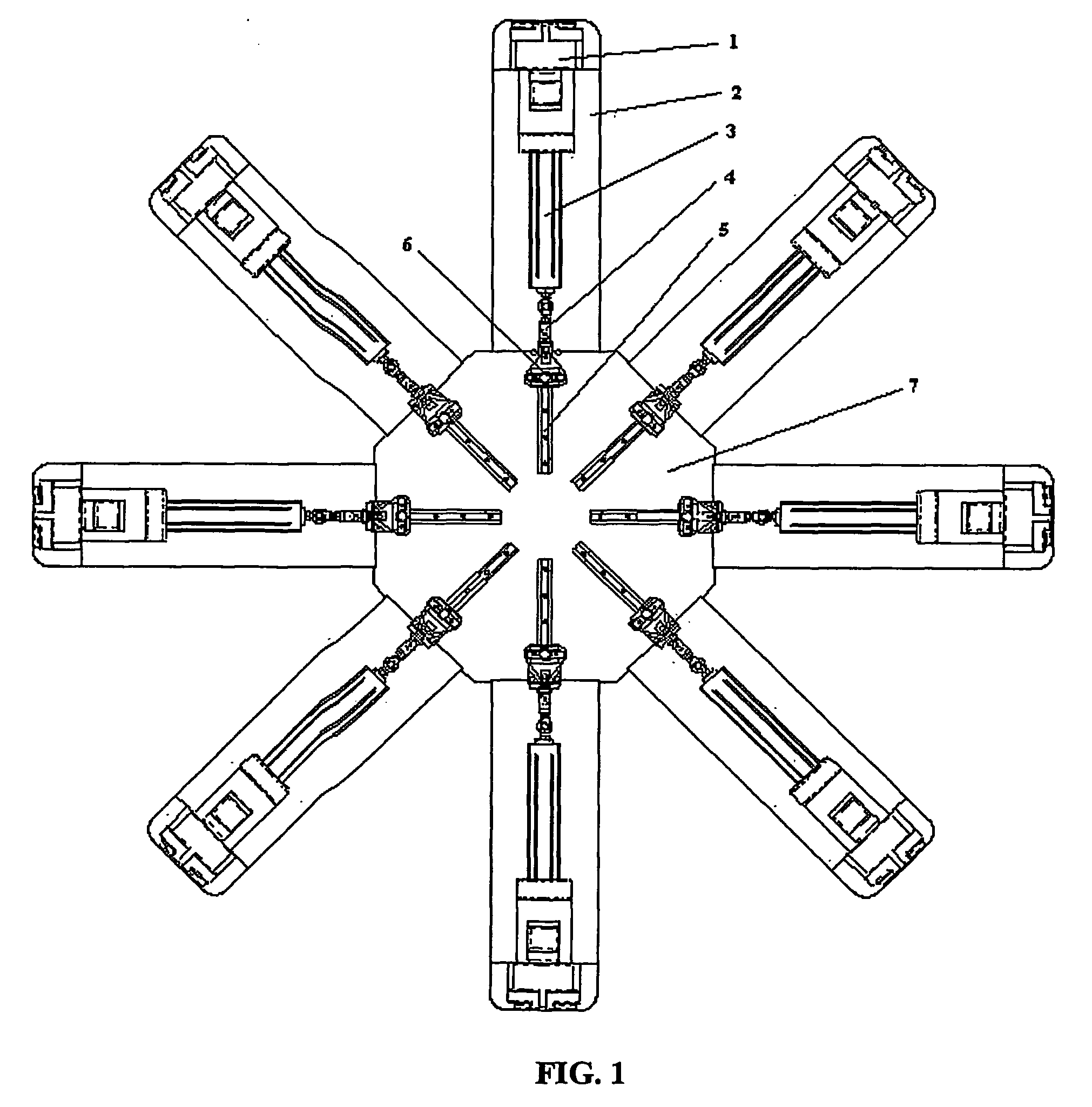
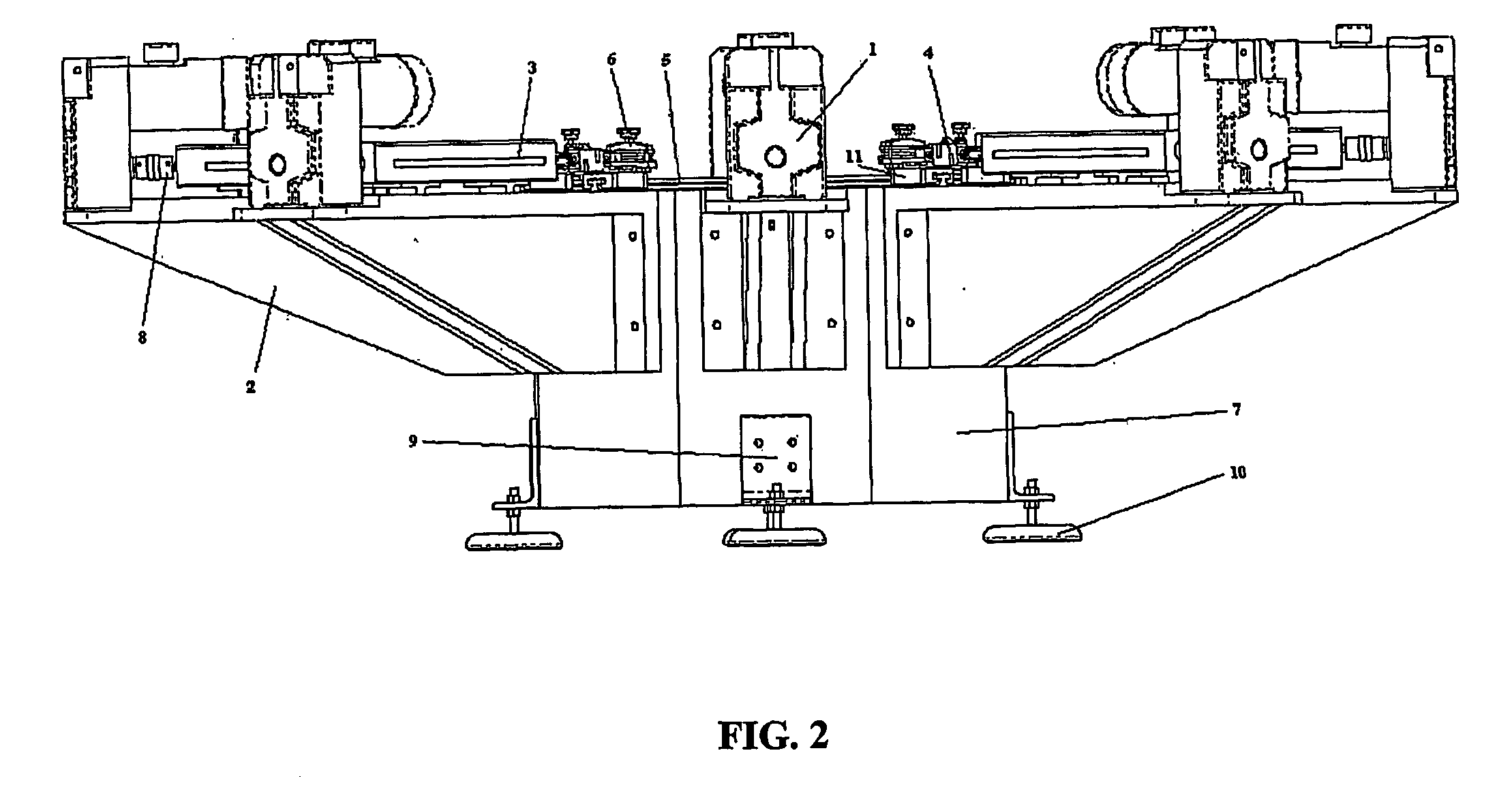
[0017]FIG. 2 is a side view of the testing machine, showing another view of the central block 7, which is supported by 4 anti-vibration mounts 10 to regulate the machine levelling and to stabilize t...


PUM

PropertyMeasurementUnit
tensileaaaaaaaaaa
forceaaaaaaaaaa
displacementaaaaaaaaaa

Abstract

The invention concerns a multiaxial universal testing machine, which allows evaluating the mechanical behaviour and performance of materials with planar structures, such as fabrics, composites and laminates. The machine comprises 4 horizontal axes at 45°, with 8 gripping jaws displaceable along slide rails and moved by the action of 8 independent motors. The connection between a gripping jaw and its respective motor is assured by a linear actuator. The test specimen is fixed by the gripping jaws and can be subject to tensile, compression and fatigue testing, making possible the analysis of the materials behaviour under simultaneous multi-directional loads.

Description

BACKGROUND OF THE INVENTION[0001]The present invention relates generally to universal testing machines and more specifically to methods for applying a multiaxial load to a planar test specimen. Actually, there is no equipment capable to evaluate some behaviour parameters, like tensile, compression or fatigue, in different directions simultaneously. As alternative, the evaluation of these characteristics has been done resorting to the unidirectional dynamometer, doing the assays only in one direction or successively in each direction. In this case the results don't give any indication about the interaction of the multiaxial forces.[0002]In known testing machines of that kind, we observe a frame with an upper transverse member and a base transverse member as well as two interconnecting guide pillars in way to tensile compression and beading testing operations. A central transverse member is displaceable along the guide pillars, while testing devices can be connected between upper and ...

Claims


Application Information

Patent Timeline
Patent Type & Authority Applications(United States)
IPC IPC(8): G01N3/08G01N3/00G01N3/02
CPCG01N3/08G01N2203/0016G01N2203/0073G01N2203/0282G01N2203/025G01N2203/0254G01N2203/0278G01N2203/0085
Inventor MONTEIRO, JOAO LUIS MARQUES PEREIRADA ROCHA, ANA MARIA MOREIRA FERREIRALIMA, MARIO FILIPE ARAUJO GONCALVESMARTINS, JULIO MANUEL DE SOUSA BARREIROSARAUJO, MARIO DUARE DECOUTO, CARLOS ALBERTO CARIDADE MONTEIROMENDES, FERNANDO JORGE DE CASTRO VIEIRA
Owner UNIVERSITY OF MINHO
Why Eureka
Try Eureka