Electric power steering apparatus

a technology of electric power steering and steering shaft, which is applied in the direction of gearing details, gearing, transportation and packaging, etc., can solve the problems of increasing the amount of backlash between the worm and the worm wheel, the iner diameter of the bearing holding hole is enlarged, and the sound of tooth striking is increased, so as to prevent the position of the bearing, reduce the amount of backlash between the driving gear and the driving gear, and reduce the effect of increasing the rotational resistance between the driving gear

Inactive Publication Date: 2008-02-14
JTEKT CORP
View PDF8 Cites 4 Cited by
  • Summary
  • Abstract
  • Description
  • Claims
  • Application Information

AI Technical Summary

Benefits of technology

[0010]On the other hand, a direction in which the bearing is pressed by a reaction force of mesh from the driving gear received by the driven gear is parallel to the direction in which the center-to-center distance increases. Even if a very small clearance exists between the inner periphery of the bearing holding hole and the bearing, therefore, the position of the bearing is prevented from being undesirably shifted within the bearing holding hole. As a result, the amount of backlash between the driving gear and the driven gear can be properly maintained.
[0011]The urging member urges at least one of the first bearing and the second bearing in the direction in which the center-to-center distance increases. Even when the amount of expansion of the driven gear due to temperature rise is larger than the amount of expansion of the housing, therefore, the amount of backlash between the driving gear and the driven gear is not excessively reduced. Consequently, the increase in rotational resistance between the driving gear and the driven gear can be restrained irrespective of temperature changes. As a result, a good steering feeling can be obtained.

Problems solved by technology

When the electric power steering apparatus is employed for a long time period, however, the inner diameter of the bearing holding hole is enlarged.
When the clearance occurs, the amount of backlash between the worm and the worm wheel is increased.
As a result, a tooth striking sound is increased, so that noises become a problem.
When the amount of thermal expansion of the worm wheel due to temperature rise is larger than the amount of thermal expansion of the housing, the amount of backlash is increased as the temperature rises.
Therefore, a rotational resistance between the worm and the worm wheel is increased, resulting in a degraded steering feeling.

Method used


Image

  • Electric power steering apparatus
  • Electric power steering apparatus
  • Electric power steering apparatus

Examples


specific example 1

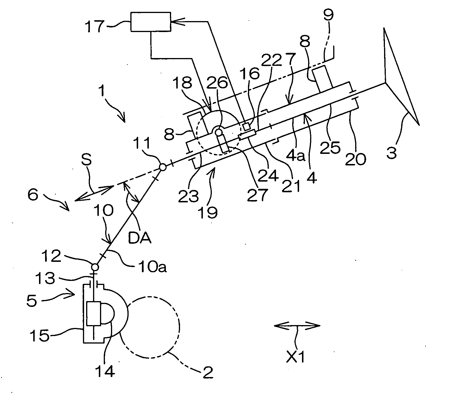
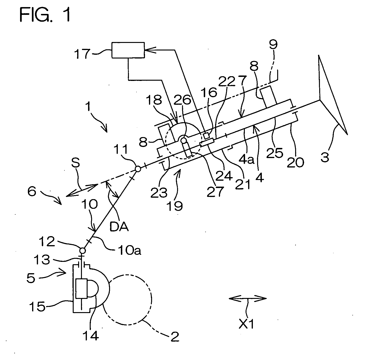
[0057]Referring to FIGS. 1 and 2, the worm shaft 26 extends in a transverse direction, and is positioned just above (or just below) the worm wheel 27 in the specific example 1. Further, the power transmission shaft 10 in the intermediate shaft 6 is a non-telescopic shaft.

[0058]The steerable wheel 2 receives an external force from a road surface. The external force is transmitted to the second bearing 29 through the steering mechanism 5, the intermediate shaft 6, and the output shaft 23 in the first steering shaft 4. The external force is exerted to push and pull the power transmission shaft 10 of the intermediate shaft 6 in its axial direction. The maximum value of an external force received by the power transmission shaft 10 in its axial direction is set to 640 N. Note that this value is used for a durability test and is so large that the external force is not exerted at the time of normal use of the electric power steering apparatus 1.

[0059]In FIG. 1, the maximum value of an angle...

specific example 2

[0062]A specific example 2 differs from the specific example 1 in that the power transmission shaft 10 in the intermediate shaft 6 comprises a telescopic shaft. In the specific example 2 in which the power transmission shaft 10 comprises a telescopic shaft, a force from the power transmission shaft 10 received by the first steering shaft 4 is reduced to approximately one-third of that in the specific example 1.

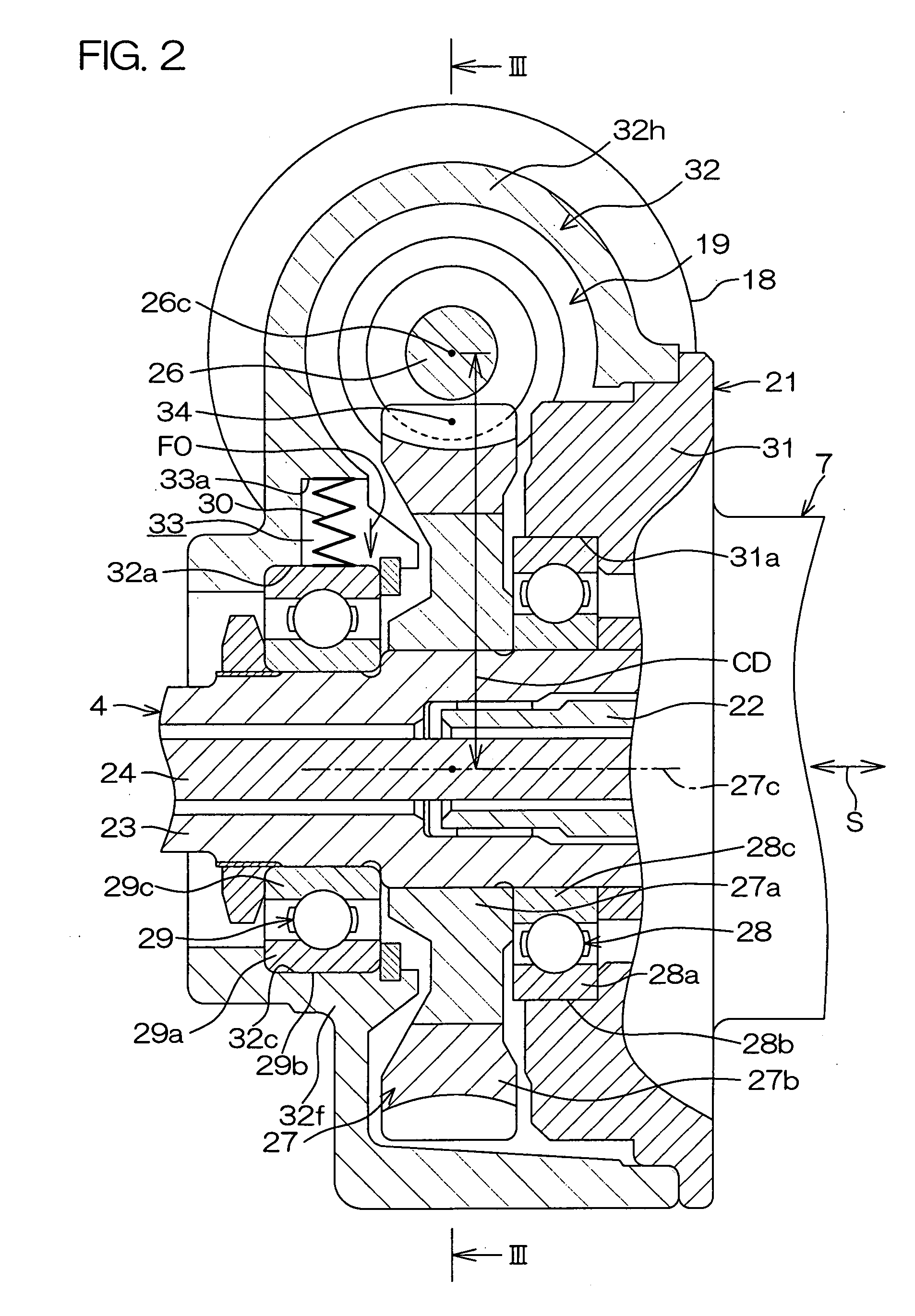
[0063]For example, a maximum value G2 of a force exerted in a radial direction of the second bearing 29 from the first steering shaft 4 is 100 N. In order that the second bearing 29 does not move when it receives an external force from the first steering shaft 4, therefore, the magnitude of an urging force produced by the urging member 30 must be not less than the maximum value G2 of the above-mentioned force, i.e., a magnitude of not less than 100 N.

specific example 3

[0064]In a specific example 3, the worm shaft 26 extends in a longitudinal direction, and is arranged right beside the worm wheel 27. Further, the power transmission shaft 10 in the intermediate shaft 6 comprises a telescopic shaft.

[0065]In the specific example 3, a maximum value G3 of a force exerted in a radial direction of the second bearing 29 from the first steering shaft 4 is also 100 N, as in the specific example 2. On the other hand, the urging member 30 urges the second bearing 29 in a direction perpendicular to the direction of the force.

[0066]In order that the second bearing 29 does not move when it receives an external force from the first steering shaft 4, therefore, not less than the half of the above-mentioned maximum value G3 (100N), i.e., a magnitude of not less than 50 N is sufficient as the magnitude of an urging force produced by the urging member 30.

[0067]When the magnitude of the urging force produced by the urging member 30 is set in each of the above-mentione...


PUM


Abstract

An electric power steering apparatus comprises a driving gear driven by an electric motor for steering assist and a driven gear meshed with the driving gear. A steering shaft is rotated along with the driven gear. The steering shaft is rotatably supported by a first bearing and a second bearing. An urging member is arranged in a recess provided in a housing. The urging member urges at least one of the first bearing and the second bearing in a direction in which a center-to-center distance between the driving gear and the driven gear increases.

Description

BACKGROUND OF THE INVENTION[0001]1. Field of the Invention[0002]The present invention relates to an electric power steering apparatus.[0003]2. Description of Related Art[0004]An electric power steering apparatus has an electric motor for generating a steering assist force and a reduction gear mechanism for decelerating the rotation of an output shaft of the electric motor. The reduction gear mechanism has a worm serving as a driving gear connected to the output shaft of the electric motor and a worm wheel serving as a driven gear meshed with the worm. The worm wheel is fixed to a steering shaft. The steering shaft is rotatably supported by a bearing. The bearing is held in a bearing holding hole of a housing (see Japanese Unexamined Patent Publication No. 2005-280589).[0005]In the electric power steering apparatus, a proper amount of backlash is usually provided between the worm and the worm wheel at the time of factory shipment. When the electric power steering apparatus is employe...

Claims


Application Information

Patent Timeline
Patent Type & Authority Applications(United States)
IPC IPC(8): B62D5/04
CPCB62D5/0409F16H1/16Y10T74/19828F16H2057/0213F16H55/24
Inventor IMAGAKI, SUSUMUYAMADA, WATARU
Owner JTEKT CORP
Why Eureka
Try Eureka