Muffler diffuser

a technology of muffler and insert, which is applied in the direction of thermometer, fuel injection apparatus, instruments, etc., can solve the problems of increased noise produced by such engines, reduced horsepower, lack of power, etc., and achieves the effect of reducing the decibels of noise produced, reducing noise and back pressure attendant to engine operation

Inactive Publication Date: 2008-02-14
MOORE JUSTIN
View PDF33 Cites 4 Cited by
  • Summary
  • Abstract
  • Description
  • Claims
  • Application Information

AI Technical Summary

Benefits of technology

[0011]The advantage of the present invention is that it provides an improved muffler diffuser insert designed for insertion into factory or aftermarket mufflers, and that is universal to various manufacturers of mufflers.
[0012]A further advantage of the present invention is that it provides an improved muffler diffuser insert which not only allows engine exhaust gases freely, but also lowers the decibels of the noise produced below an acceptable level.
[0013]Yet another advantage of the present invention is that it provides an improved muffler diffuser insert adapted to be used with an exhaust system for effectively helping to reduce noise and back pressure attendant to engine operation, and, more particularly, an improved muffler diffuser insert which is virtually free-flowing, but which will not restrict an outgoing exhaust air flow.
[0014]A still further advantage of the present invention is to provide an improved muffler diffuser insert that fits into a factory or aftermarket muffler without “plugging up” the muffler and causing back pressure and overheating of the muffler to build.

Problems solved by technology

In a 2-stroke motor, it is the mixture of gas and oil that is burned in the combustion chamber and then exhausted into our air that creates an environmental issue.
On the platform of this newly designed motor, however, manufacturers needed to increase the engine compression, which also increased the amount of noise that such engines produce.
If the muffler caused additional back pressure it would result in various complications—i.e.
: reduction of horsepower, lack of power, overheating and premature valve failure.
However, some conventional muffler inserts, during use, do not adequately allow for sufficient exhaust flow, thus “plugging up” the muffler and causing back pressure to build, and overheating of the muffler to occur to a certain degree.

Method used


Image

  • Muffler diffuser
  • Muffler diffuser
  • Muffler diffuser

Examples


Embodiment Construction

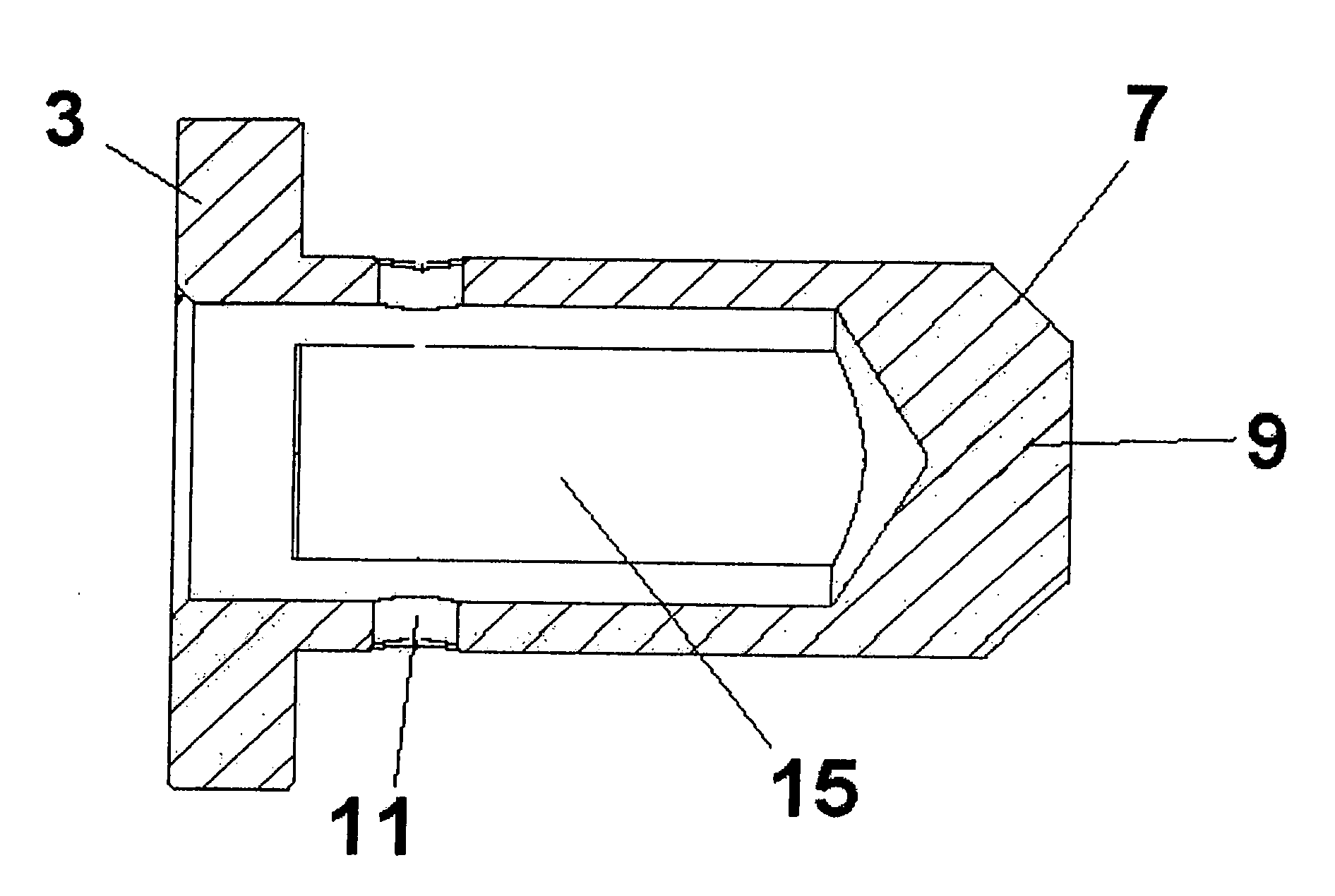
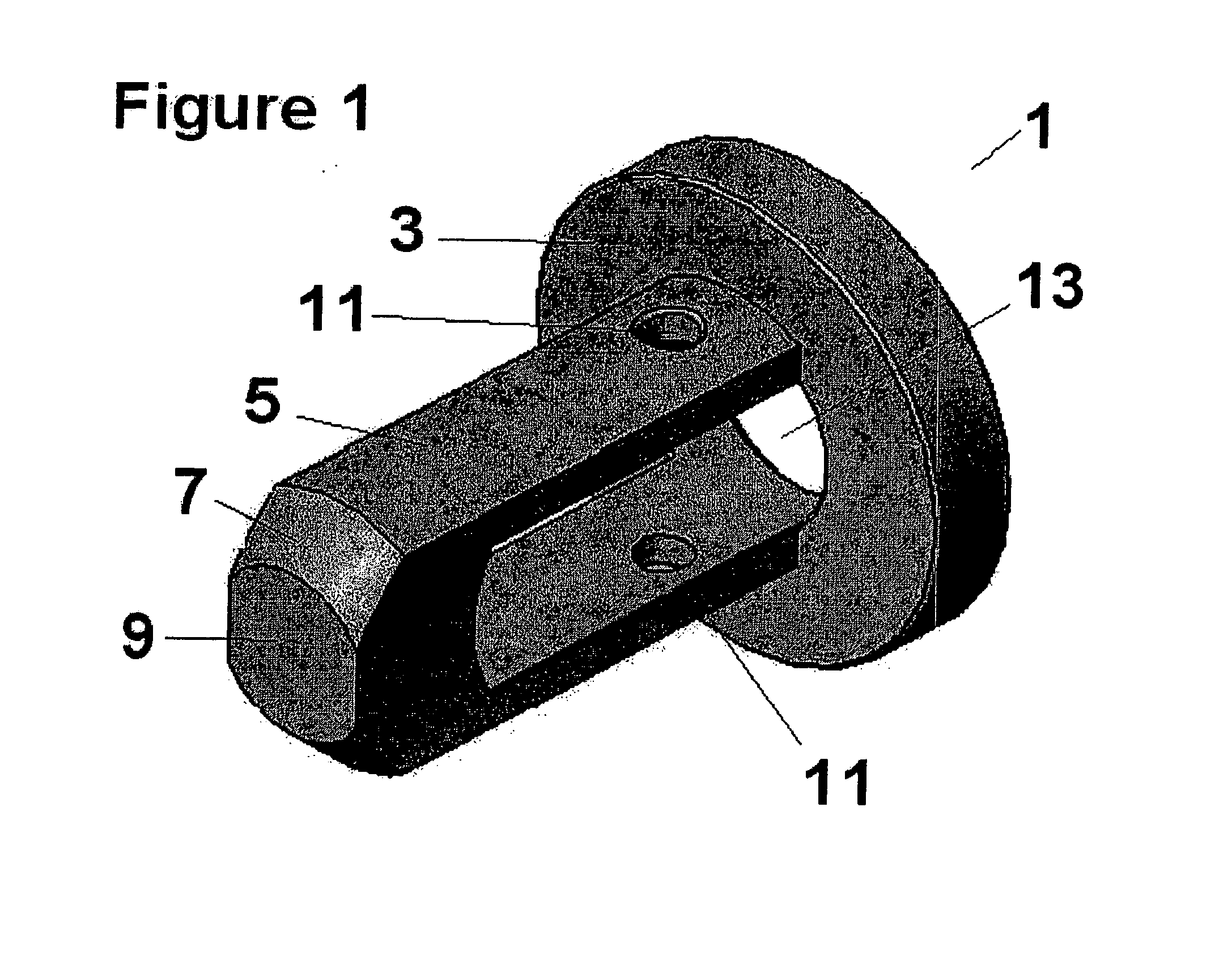
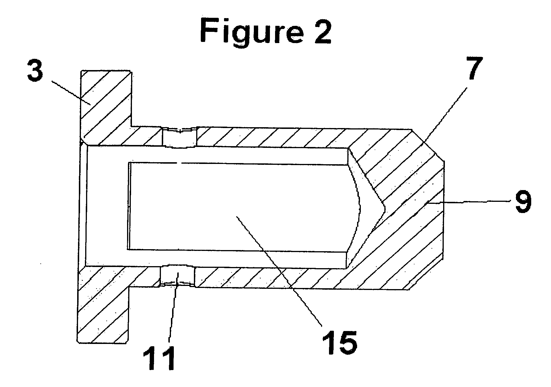
[0020]FIG. 1 broadly illustrates the muffler diffuser insert 1 of the present invention, which essentially comprises a body portion 5 integrally connected to a cap end 3, in a preferred embodiment, or which connection can be accomplished through welding or through other means which would be apparent to a worker skilled in the art. It can also be seen in FIG. 1 that the cap end is perpendicularly positioned in relation to the body portion. Preferably, the body portion 5 is elongated, and is perpendicularly positioned in relation to the cap end 3. As can be seen in FIG. 2, the body portion 5 also defines therein an opening 15, which will be described hereinafter, and possesses an insertion end 9, distally opposed from the cap end 3, which is meant for placement within a muffler. Further, the insertion end 9 further possesses sound deflection portions 7, which are positioned on either side of the outmost point of insertion end 9, such angled portions being placed, preferably, at a 45° ...


PUM


Abstract

An improved muffler diffuser insert adapted to be used with, and mounted within, an exhaust muffler for effectively helping to reduce noise and back pressure attendant to engine operation. The diffuser comprises a cap end for abutting against an exhaust end of the muffler when the muffler diffuser is mounted within the muffler, which has at least one exhaust opening defined therein for cooperation with the exhaust end of the muffler so as to permit an exhaust flow from the exhaust end of the muffler to pass through. A body portion is connected to the cap end, and defines therein an elongated opening for permitting the exhaust flow from the muffler to pass through. A distal end of the body portion comprises an outermost end and two sound deflection portions positioned on either side of the outermost end for use in deflecting sound waves contained in the exhaust flow so as to enhance noise diffusion.

Description

BACKGROUNDRelated Application[0001]This application claims priority to Canadian Patent Application No. 2,545,971, filed on May 9, 2006, the contents of which are incorporated herein by reference in their entirety for all purposes.FIELD OF THE INVENTION[0002]This invention relates to an improved muffler diffuser insert adapted to be used with an exhaust system for effectively helping to reduce noise and back pressure attendant to engine operation, and, more particularly, an improved muffler diffuser insert which is virtually free-flowing, causes little to no back pressure, but which will not restrict an exhaust air flow.DESCRIPTION OF THE PRIOR ART[0003]In 2000, for example, motorcycle manufacturers designed and built a four stroke race motorcycle for off-road use. The reason for them to do this was to counteract the growing concerns that the engines of previous models of 2-stroke bikes were causing harm to our environment. In a 2-stroke motor, it is the mixture of gas and oil that i...

Claims


Application Information

Patent Timeline
Patent Type & Authority Applications(United States)
IPC IPC(8): F01N1/00
CPCF01N1/083F01N1/10F01N13/082F02M2200/9076F01N13/1855F01N2590/04F01N13/16
Inventor MOORE, JUSTIN
Owner MOORE JUSTIN
Why Eureka
Try Eureka