Controller for motor

a technology for controlling devices and motors, which is applied in the direction of motor/generator/converter stoppers, dynamo-electric converter control, and dynamo-electric converter control. it can solve the problems of constructive interference between the permanent magnet of the first rotor and the permanent magnet of the second rotor, so as to improve prevent the demagnetization of the permanent magnet of the rotor. it achieves the effect of increasing the strength of the composite field

Inactive Publication Date: 2008-02-14
HONDA MOTOR CO LTD
View PDF4 Cites 59 Cited by
  • Summary
  • Abstract
  • Description
  • Claims
  • Application Information

AI Technical Summary

Benefits of technology

[0025]Furthermore, according to the fifth aspect of the invention, if it is determined in the demagnetization determining step that demagnetization of the permanent magnets of the rotors occurs, the phase difference changing driving means is controlled to change the phase difference between the rotors from the current phase difference to the phase difference that results in a higher strength of the composite field in the rotor phase difference controlling step. In this case, at the phase difference that results in a higher strength of the composite field, the magnetic fluxes of the permanent magnet of the first rotor and the permanent magnet of the second rotor constructively interfere with each other. As a result, demagnetization of the permanent magnets of the rotors can be prevented.

Problems solved by technology

In this case, at the phase difference that results in a higher strength of the composite field, the magnetic fluxes of the permanent magnet of the first rotor and the permanent magnet of the second rotor constructively interfere with each other.

Method used


Image

  • Controller for motor
  • Controller for motor
  • Controller for motor

Examples


Embodiment Construction

[0039]An embodiment of the present invention will be described with reference to FIGS. 1 to 12.

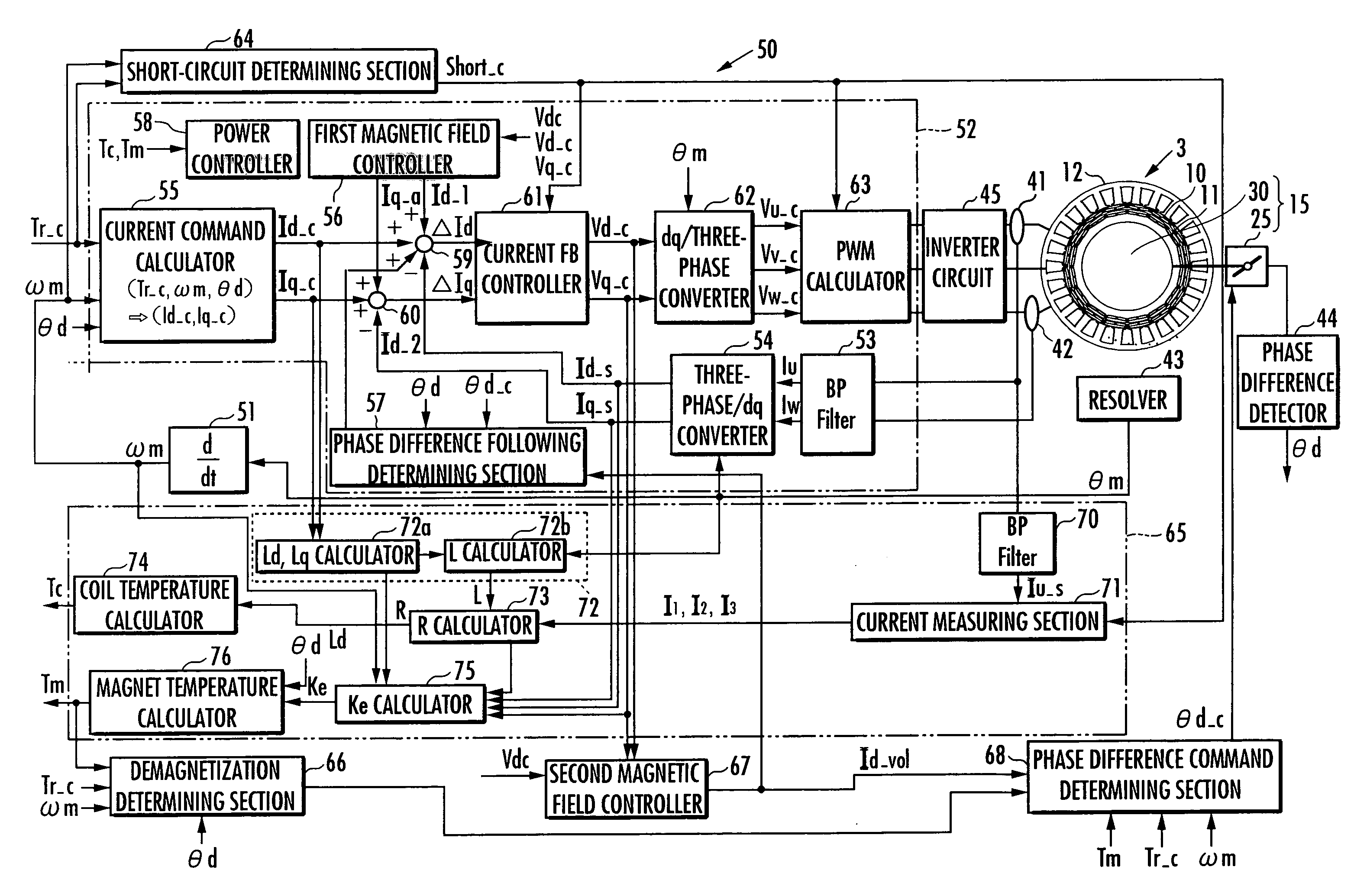
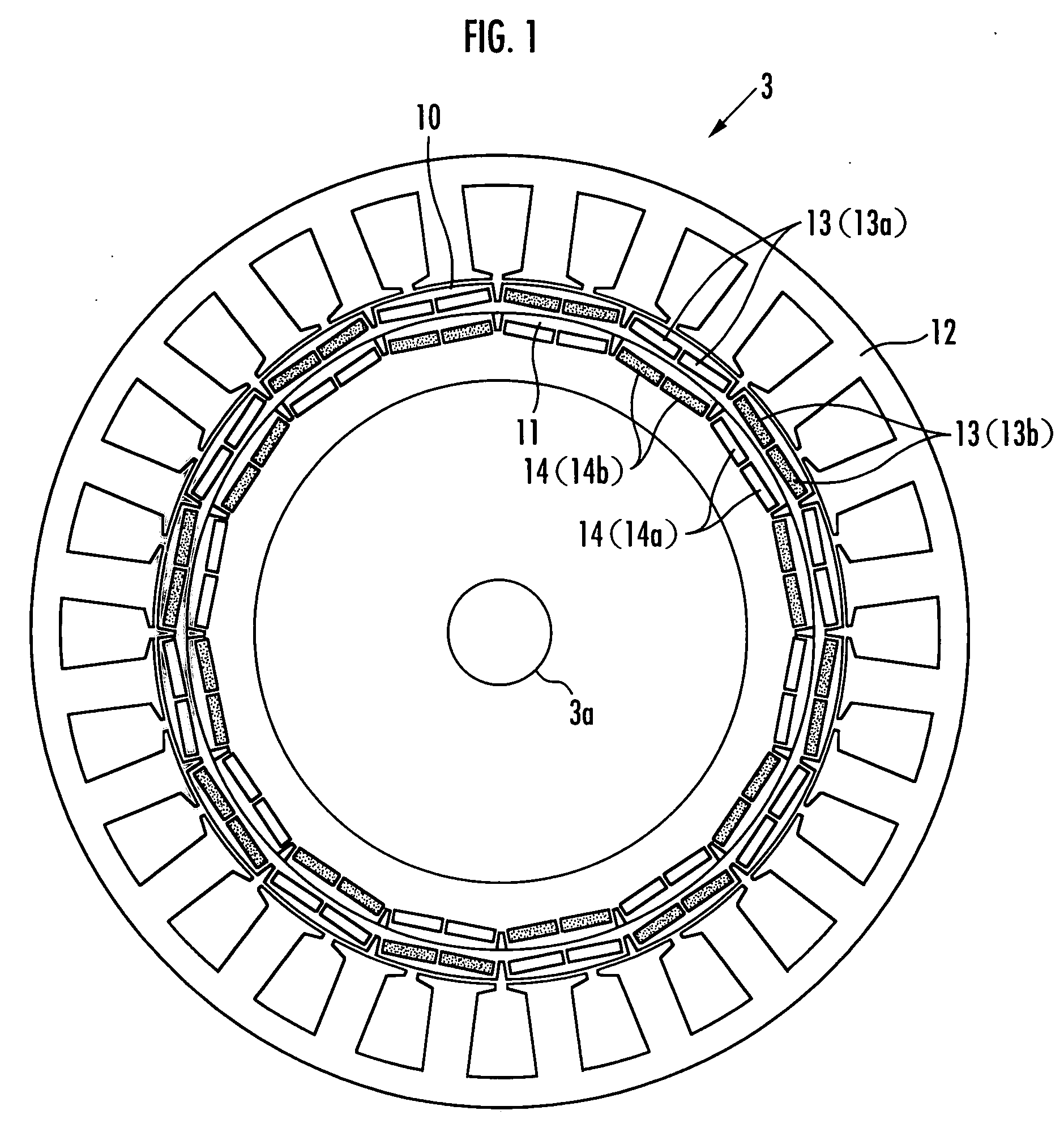
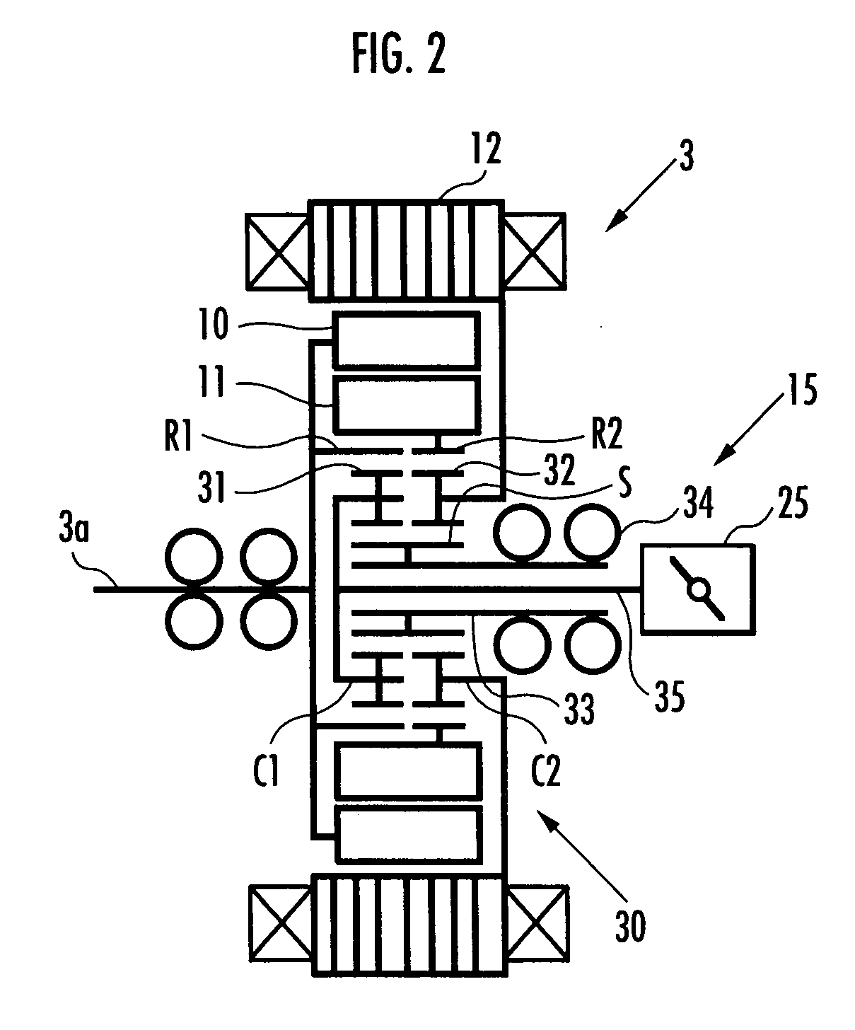
[0040]FIG. 1 is a diagram showing essential parts of the inner structure of a motor 3, which is seen along the axis of the motor 3. FIG. 2 is a skeleton diagram showing a driving mechanism for changing the phase difference between two rotors of the motor 3. In FIG. 1, illustration of the driving mechanism is omitted.

[0041]Referring to FIG. 1, the motor 3 is a DC brushless motor of a double rotor structure and has an outer rotor 10, which is a first rotor, and an inner rotor 11, which is a second rotor, which are disposed coaxially with an output shaft 3a. A stator 12 is disposed at the outer side of the outer rotor 10 and fixed to a housing (not shown) of the motor 3, and armatures (armatures of three phases, not shown) are attached to the stator 12.

[0042]The outer rotor 10 has an annular shape and has a plurality of permanent magnets 13 disposed at regular intervals along the circumferenc...


PUM


Abstract

There is provided a controller for a motor capable of changing the phase difference between two rotors that can prevent demagnetization of permanent magnets or the rotors. The motor has two rotors each having a permanent magnet and phase difference changing driving means for changing the phase difference between the rotors. The controller has a demagnetization determining means for determining whether or not demagnetization of the permanent magnets of the rotors occurs during operation of the motor, and rotor phase difference controlling means for controlling the phase difference changing driving means to change the phase difference between the rotors from a current phase difference to a phase difference that results in a higher strength of a composite field of the permanent magnets if the result of determination by the demagnetization determining means is positive.

Description

BACKGROUND OF THE INVENTION[0001]1. Field of the Invention[0002]The present invention relates to a controller for a motor that has two rotors each having a permanent magnet to produce a field and can change the phase difference between the rotors.[0003]2. Description of the Related Art[0004]As a permanent magnet type motor, there has been known a double rotor type motor that has two rotors that are coaxially disposed and each have a permanent magnet for producing a field (for example, see Japanese Patent Laid-Open No. 2002-204541 (referred to as Patent Document 1 hereinafter)). In the motor of this type, the two rotors can relatively rotate with respect to each other about the axis thereof, and the phase difference between the rotors can be changed by the relative rotation. By changing the phase difference between the rotors, the strength of a composite field (the magnitude of magnetic fluxes) of the fields produced by the permanent magnets of the rotors can be changed.[0005]The mot...

Claims


Application Information

Patent Timeline
Patent Type & Authority Applications(United States)
IPC IPC(8): H02P6/08H02P21/00H02K1/27H02K21/14H02P6/06H02P6/17H02P6/28H02P21/06H02P21/08H02P21/14H02P21/18H02P21/22H02P21/24H02P21/32H02P23/00H02P23/06H02P23/14H02P25/02H02P27/08
CPCH02P21/0003
Inventor KAIZUKA, MASAAKIATARASHI, HIROFUMIFUKUCHI, MASANARIFURUKAWA, KATSUHIKO
Owner HONDA MOTOR CO LTD
Why Eureka
Try Eureka