Battery device

a battery device and battery technology, applied in secondary cell servicing/maintenance, cell components, nickel accumulators, etc., can solve the problems of difficult to charge the battery cell to full power, long charging time of the battery device, and complicated structure of the charger, so as to reduce the charging time and the effect of sufficient power

Inactive Publication Date: 2008-02-14
SONY CORP
View PDF0 Cites 70 Cited by
  • Summary
  • Abstract
  • Description
  • Claims
  • Application Information

AI Technical Summary

Benefits of technology

[0013]Therefore, it is desirable to provide a battery device that is advantageous in charging a battery cell to sufficient power thereof while reducing a charging time by adjusting a charging current according to the temperature of the battery cell in the battery device and adjusting the temperature to temperature optimum for charging.
[0015]With the battery device according to the embodiment of the present invention, when it is detected that the temperature of the battery cell deviates from a predetermined temperature range suitable for charging, since the second current split from the externally-supplied charging current is supplied to the temperature control unit, it is possible to adjust the temperature of the battery cell to be within the predetermined temperature range. Consequently, it is possible to supply a charging current of a sufficient magnitude to the battery cell. This is advantageous in charging the battery cell to sufficient power thereof while reducing a charging time.

Problems solved by technology

Therefore, at the time of a low temperature and a high temperature, it takes long to charge the battery device.
Since the charging condition is not optimum, it is difficult to charge the battery cell to full power thereof.
Since these operations are performed on a charger side and a charging amount is controlled by a circuit in the charger, a structure of the charger is complicated.
Thus, it is difficult to adjust an optimum condition for every battery on the charger side.

Method used


Image

  • Battery device
  • Battery device
  • Battery device

Examples


first embodiment

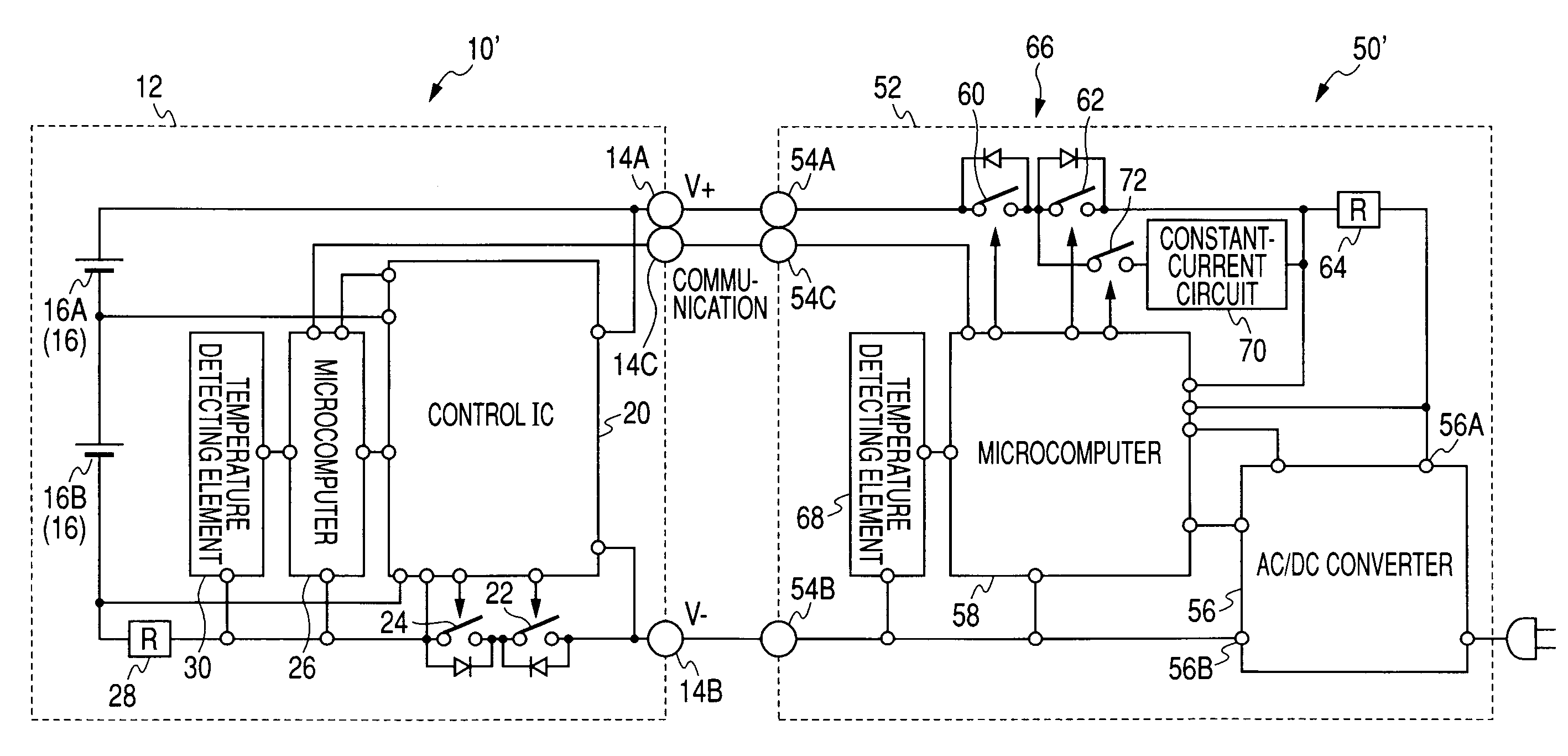
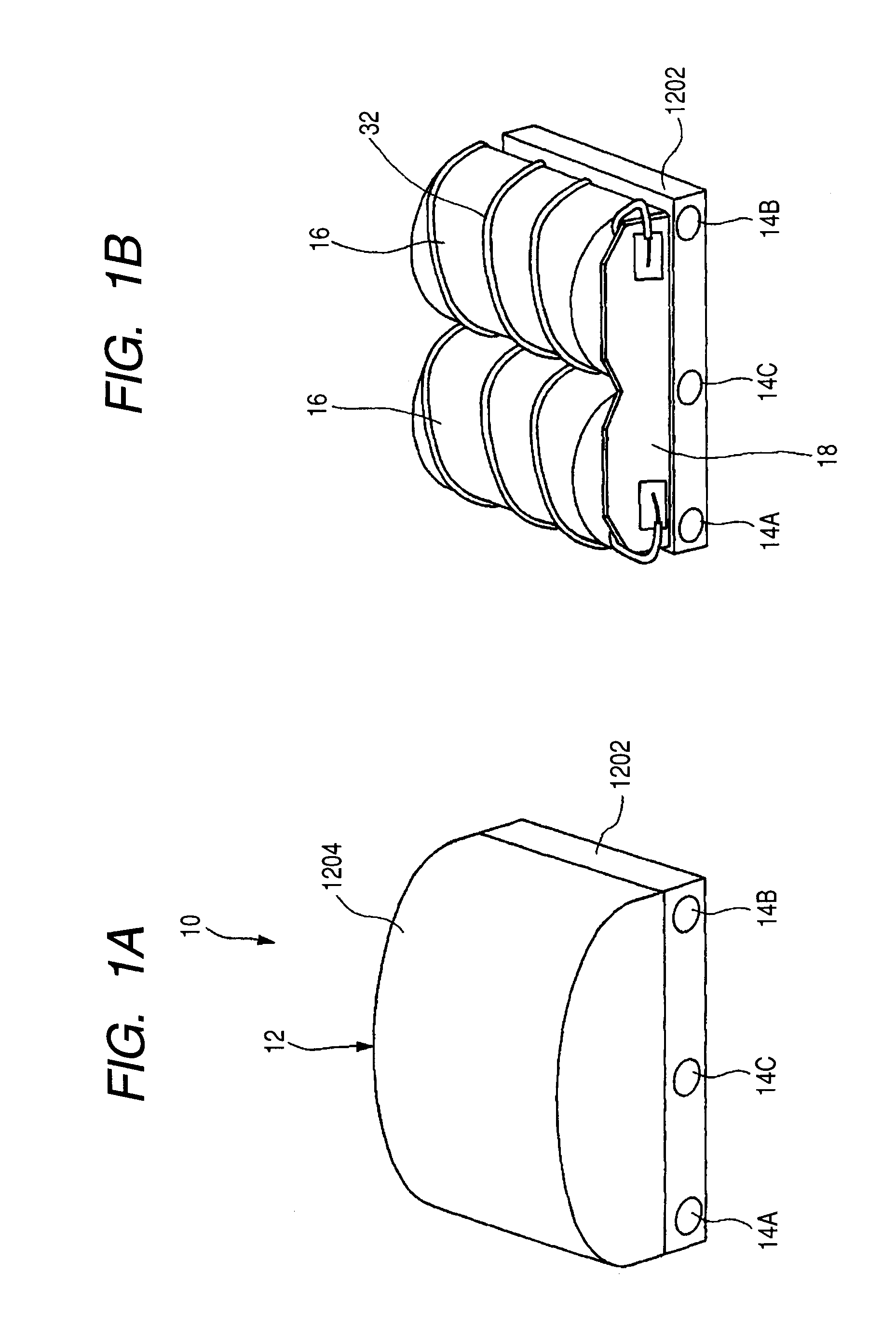
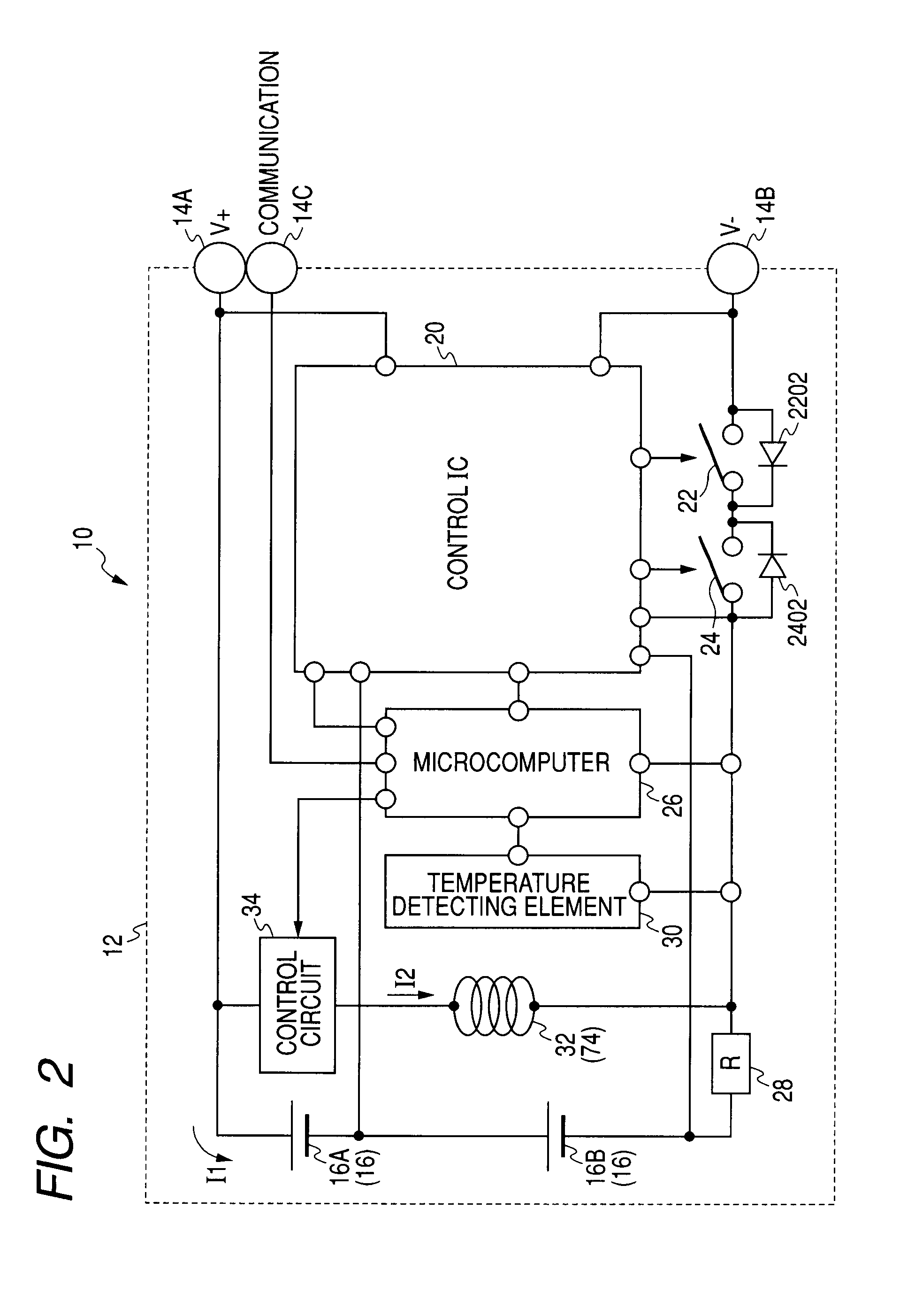
[0043]A battery device 10 according to a first embodiment of the present invention will be explained. FIG. 1A is a perspective view of the battery device 10 and FIG. 1B is a perspective view of the battery device 10 from which an upper case 1204 is removed. FIG. 2 is a block diagram showing a structure of the battery device 10. FIG. 3 is a block diagram showing a state in which the battery device 10 is mounted on the charger 50 and charged.

[0044]As shown in FIG. 1A, the battery device 10 has a case 12. The case 12 is constituted by connecting a lower case 1202 assuming a rectangular tabular shape and an upper case 1204 having four sides connected to four edges of the lower caser 1202 and an upper surface that connect upper portions of the four sides.

[0045]On one side of the lower case 1202, a battery-side positive electrode terminal 14A, a battery-side negative electrode terminal 14B, and a battery-side communication terminal 14C connected to a positive electrode terminal, a negativ...

second embodiment

[0143]A second embodiment of the present invention is different from the first embodiment in that the battery cells 16 are cooled at a high temperature.

[0144]FIG. 9A is a perspective view of the battery device 10 according to the second embodiment. FIG. 9B is a perspective view of the battery device 10 from which the upper case 1204 is removed.

[0145]In the second embodiment, instead of the heater 32 in the first embodiment, a Peltier element 74 is provided as a heat absorbing element that absorbs heat to cool the battery cells 16 when an electric current is supplied thereto. In other words, in this embodiment, a temperature control unit includes the Peltier element 74.

[0146]As shown in FIG. 9B, the Peltier element 74 is provided to cover the outer periphery of the two battery cells 16. In this embodiment, as shown in FIG. 2, one end of the Peltier element 74 is connected to the battery-side positive electrode terminal 14A via the control circuit 34 and the other end is connected to ...

third embodiment

[0171]A battery device according to a third embodiment of the present invention is a combination of the battery devices according to the first and second embodiments.

[0172]FIG. 10A is a perspective view of the battery device 10 according to the third embodiment. FIG. 10B is a perspective view of the battery device 10 from which the upper case 1204 is removed. FIG. 11 is a block diagram showing a structure of the battery device 10 according to the third embodiment.

[0173]As shown in FIG. 10B, the Peltier element 74 is provided on the outer periphery of the battery cells 16 and the heater 32 is wound around the Peltier element 74. Therefore, a temperature control unit includes the heater 32 (a heat generating element) and the Peltier element 74 (a heat absorbing element).

[0174]As shown in FIG. 11, the control circuit 34 includes a first control circuit 34A that splits the second current I2 from the externally-supplied charging current to the heater 32 and a second control circuit 34B t...


PUM

PropertyMeasurementUnit
output voltageaaaaaaaaaa

Abstract

A battery device includes a battery cell constituted by a secondary cell, a case that houses the battery cell, and a battery-side positive electrode terminal and a battery-side negative electrode terminal electrically provided in the case and connected to the battery cell. The battery device further includes a temperature detecting unit that detects the temperature of the battery cell, a temperature control unit that heats and / or cools the battery cell when an electric current is supplied thereto, and a current control unit that divides, according to the temperature detected by the temperature detecting unit, an externally-supplied charging current supplied from the outside via the battery-side positive electrode terminal and the battery-side negative electrode terminal into a first current supplied to the battery cell and a second current supplied to the temperature control unit.

Description

CROSS REFERENCES TO RELATED APPLICATIONS[0001]The present invention contains subject matter related to Japanese Patent Application JP 2006-218285 filed in the Japanese Patent Office on Aug. 10, 2006, the entire contents of which being incorporated herein by reference.BACKGROUND OF THE INVENTION[0002]1. Field of the Invention[0003]The present invention relates to a battery device.[0004]2. Description of the Related Art[0005]There is a battery device (a battery pack) that has a battery cell (a rechargeable battery) constituted by a secondary cell.[0006]When the battery cell is discharged at temperature higher or lower than a predetermined temperature range, deterioration in the battery cell is quickened to reduce durable life of the battery cell.[0007]Thus, in many cases, a temperature detecting unit such as a thermistor and a control circuit that interrupts an output current outputted from an electrode terminal of the battery device according to temperature detected by the temperatur...

Claims


Application Information

Patent Timeline
Patent Type & Authority Applications(United States)
IPC IPC(8): H02J7/04H01M2/10H01M10/30H01M10/44H01M10/48H01M10/60H01M10/613H01M10/615H01M10/633H01M10/6571H01M10/6572
CPCH01M10/486H01M10/5004H01M10/5006Y02E60/124H01M10/5083H01M10/5085H01M10/5022H01M10/615H01M10/633H01M10/6571H01M10/6572H01M10/613Y02E60/10
Inventor TASHIRO, KEIMIYAJIMA, YOICHINAGASHIMA, OSAMUTAKESHITA, TOSHIO
Owner SONY CORP
Why Eureka
Try Eureka