
Liquid crystal projection system with improved image performance

a liquid crystal projection and image performance technology, applied in the field of liquid crystal projection system, can solve the problems of increasing system reliability and reducing system cost, and achieve the effects of improving image contrast, reducing the likelihood of color phase shift, and increasing the utility efficiency of primary color lights

Inactive Publication Date: 2008-02-14
ASIA OPTICAL CO INC
View PDF5 Cites 6 Cited by
  • Summary
  • Abstract
  • Description
  • Claims
  • Application Information

AI Technical Summary

Benefits of technology

[0010]The object of the present invention is to provide a liquid crystal projection system with improved image performance, which increases the utility efficiency of the primary color lights, prevents the color phase shift appearing on the projected image, and thus improves the image contrast.
[0011]Another object of the present invention is to provide a liquid crystal projection system with improved image performance, which is simple in manufacture, easy in assembly and low in cost.
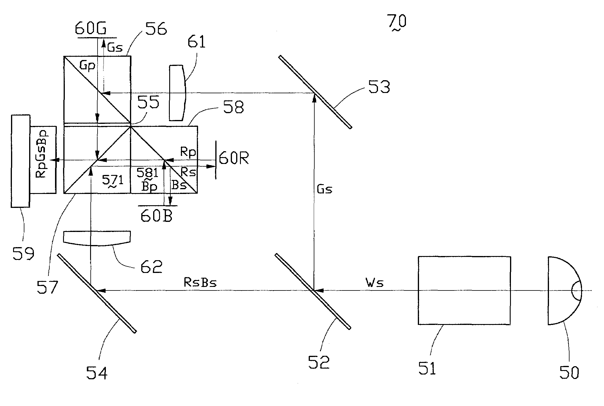
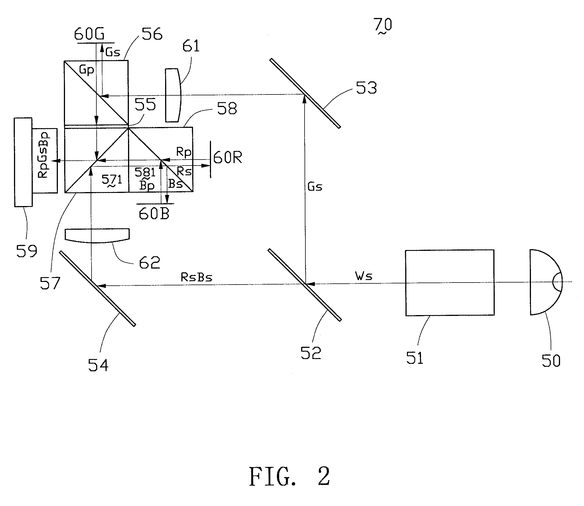
[0013]In comparison with the prior art, in the liquid crystal projection system of the present invention, the monochromatic light beam from the separating mirror is incident into the first and second polarization separators in an S-polarization state, and the bichromatic light beam from the separating mirror is incident into the second polarization separator and the color separator also in an S-polarization state. This significantly increases the utility efficiency of the primary color lights from the light source, effectively decreases the likelihood that color phase shift occurs and improves the image contrast, whereby the projection image performance of the present system is increased. Further, the liquid crystal projection system of the present invention achieves the light polarization and separation functions by employing two polarization separators and one color separator that are cemented together as an L-shaped prism module. Within the L-shaped prism module, no additional optical elements are arranged therebetween except for a half-wave plate, which decreases the system cost and increases the system reliability. This L-shaped prism module may be composed of six, five or even four conventional isosceles right-angle prisms. Therefore, liquid crystal projection system of the present invention also has the advantages of simple manufacture, easy assembly and low cost.

Problems solved by technology

Within the L-shaped prism module, no additional optical elements are arranged therebetween except for a half-wave plate, which decreases the system cost and increases the system reliability.

Method used


Image

  • Liquid crystal projection system with improved image performance
  • Liquid crystal projection system with improved image performance
  • Liquid crystal projection system with improved image performance

Examples


first embodiment

[0019]Referring to FIG. 2, a liquid crystal projection system constructed in accordance with the present invention, generally designated with reference numeral 70, comprises a light source 50 for emitting white light, a polarizer 51 for polarizing the white light so as to obtain a polarized light beam, a separating mirror 52 for providing separated light beams, first and second reflecting mirrors 53, 54 for light reflection, a half-wave plate 55 (λ / 2 wave plate, λ=632.8 nm) for transforming the polarization of an incident light beam, first and second polarization separators 56, 57 for polarization splitting, a color separator 58, an image modulation device 60 for light modulation and transformation, and a projection lens 59 for projecting the output light beam onto a screen. The polarizer 51 is disposed on an output light path of the light source 50 for polarizing the non-polarized incident white light into a polarized white light beam Ws (S denotes a perpendicular polarization) of ...

second embodiment

[0025]FIG. 3 shows a liquid crystal projection system 71 in accordance with the present invention. In this embodiment, the polarizer 51 outputs an S-polarized white light beam Ws of three primary colors R, Q B to the separating mirror 52. The separating mirror 52 separates the white light beam Ws into two sets of polarized light beams, a monochromatic light beam Gs and a bichromatic light beam (Rs, Bs). The separating mirror 52 reflects the monochromatic light beam Gs to the first reflecting mirror 53 positioned thereabove, and transmits the bichromatic light beam (Rs, Bs) to the second reflecting mirror 54 positioned on the left side thereof. The monochromatic light beam or green light beam Gs is reflected by the first reflecting mirror 53 to the first converging lens 61 for convergence onto the first polarization separator 56. The first polarization separator 56, in the form of a PBS, is adapted to transmit P-polarized light and reflects S-polarized light. Therefore, the green lig...


PUM


Abstract

A liquid crystal projection system (70) includes a light source (50) for emitting a white light beam of three primary colors, a polarizer (51) for polarizing the white light beam, a separating mirror (52), first and second reflecting mirrors (53, 54), first and second polarization separators (56, 57), a half-wave plate (55), a color separator (58), an image modulation device (60R, 60G, 60B) and a projection lens (59). The first polarization separator, the second polarization separator and the color separator are combined together as a unit. The half-wave plate is positioned between the first and second polarization separators. The image modulation device is arranged on sides of the first polarization separator and the color separator. The projection lens is disposed on one side of the second polarization separator. Both monochromatic and bichromatic light beams from the separating mirror are respectively incident into the first and second polarization separators in an S-polarization state.

Description

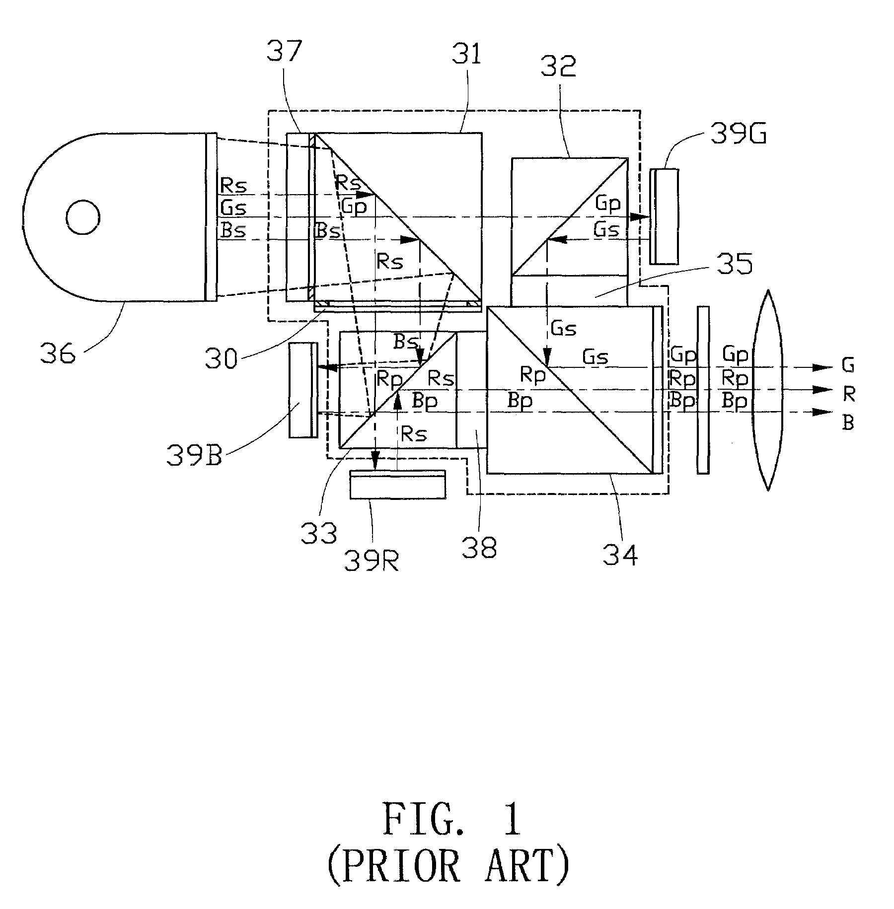
BACKGROUND OF THE INVENTION[0001]1. Field of the Invention[0002]The present invention relates to a liquid crystal projection system and in particular to a liquid crystal projection system with improved image performance, which utilizes three reflection type liquid crystal panels for image projection output.[0003]2. Description of Prior Art[0004]A liquid crystal projector can be classified into a single-panel type and a three-panel type by the number of liquid crystal panels to be used. A single-panel projector is low in resolution and brightness, but is economic in cost. A three-panel projector has the advantages of high resolution and high brightness, but is expensive in cost. The working principle for a three-panel projector is to separate a white light from a light source into three primary color lights of red (R), green (G) and blue (B), then guide the three primary color lights to enter into respective red-color, green-color and blue-color liquid crystal display panels, recombi...

Claims


Application Information

Patent Timeline
Patent Type & Authority Applications(United States)
IPC IPC(8): G03B21/14
CPCG03B21/14G03B21/2073G03B21/208G03B33/12
Inventor HSIUNG, CHIEN-CHIHLIN, KENG-HUIWU, TSI-LUNGHUNG, WEN-LANG
Owner ASIA OPTICAL CO INC
Learn More