
Display device, multi-display system, and image information generation method

a multi-display system and display device technology, applied in the field of display device, multi-display system, image information generation method, can solve the problems of complex operation setting, projectors cannot autonomously recognize information, and difficulty in constructing multi-display system, so as to achieve the effect of facilitating the processing of programs

Active Publication Date: 2008-02-14
SEIKO EPSON CORP
View PDF15 Cites 33 Cited by
  • Summary
  • Abstract
  • Description
  • Claims
  • Application Information

AI Technical Summary

Benefits of technology

[0008]An advantage of some aspects of the invention is to provide a di-splay device, a multi-display system, an image information generation method, an image information generation program, and a recording medium, all of which allow easy construction of a multi-display system.

Problems solved by technology

That is, at the time of placement of the multi-display system, using the PC is a must, and the projectors cannot autonomously recognize information needed for generation of the partial image information.
This thus complicates the operation setting, thereby resulting in a difficulty in constructing the multi-display system.
When an original image is configured by partial images that are not overlapped one another, if the projectors are not disposed appropriately, a clearance is resultantly observed among the partial images, and thus the original image cannot be satisfactorily displayed.
The issue here is that when the partial images are partially overlapped one another, and when an original image is configured thereby, in the resulting original image, the intensity value of the overlapped portions is higher than that in the remaining area, thereby resulting in a difficulty in displaying the original image with a satisfactory level.

Method used


Image

  • Display device, multi-display system, and image information generation method
  • Display device, multi-display system, and image information generation method
  • Display device, multi-display system, and image information generation method

Examples


first embodiment

[0070]In the below, a first embodiment of the invention is described by referring to the accompanying drawings.

[0071]Entire Configuration of Multi-Display System

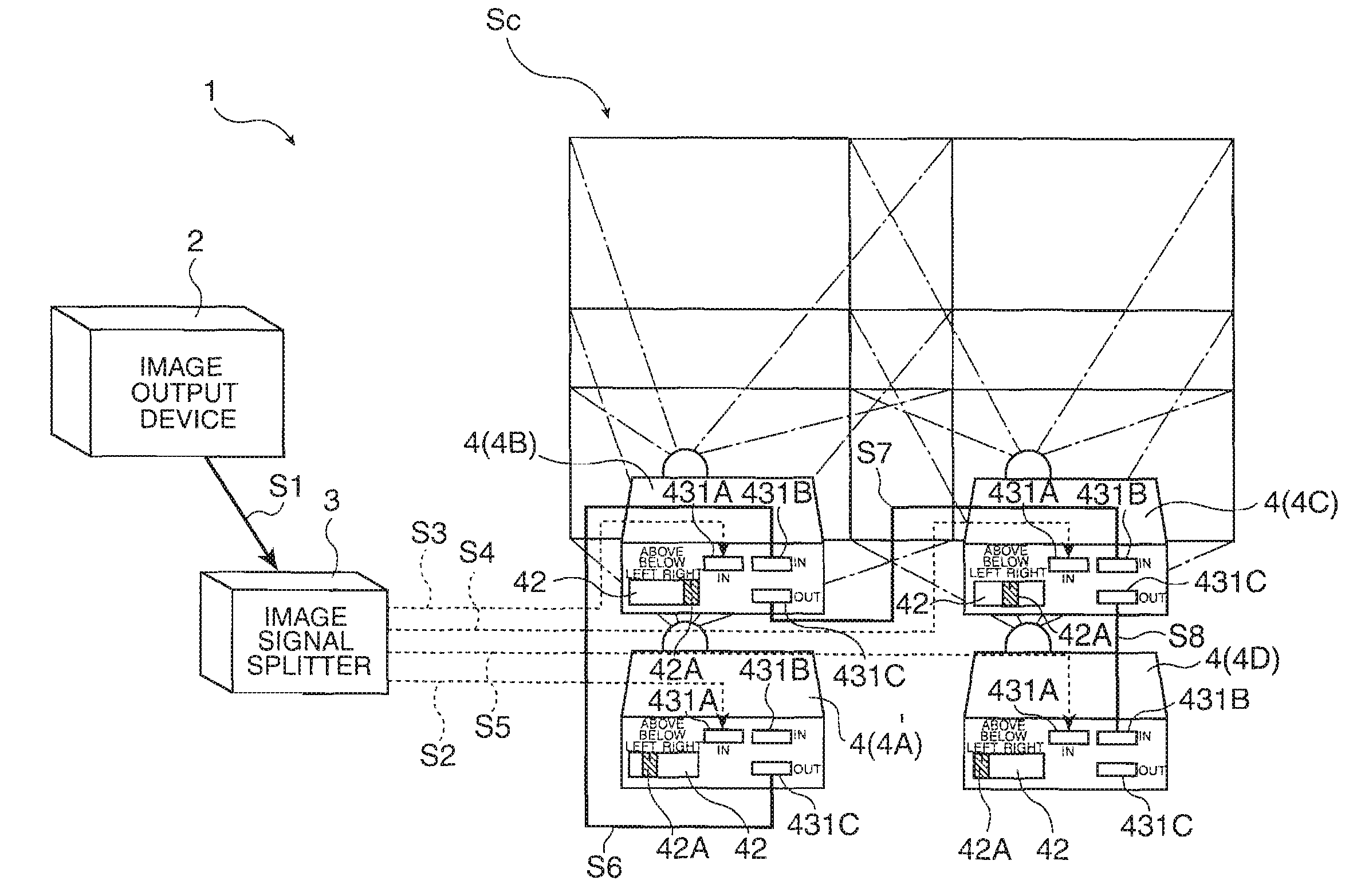
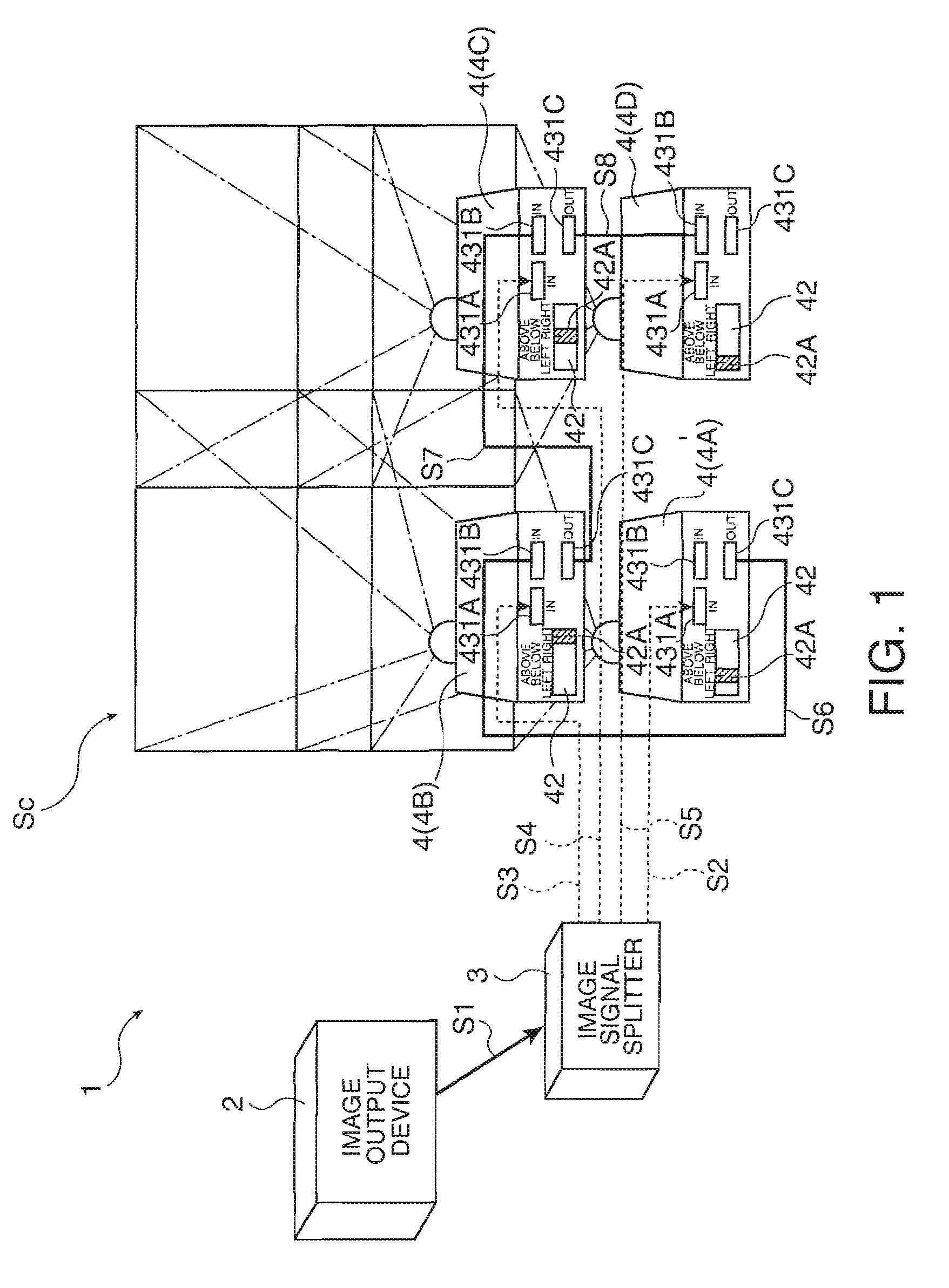
[0072]FIG. 1 is a diagram showing the configuration of a multi-display system 1.

[0073]The multi-display system 1 displays an image, i.e., original image, of high in intensity, high in resolution, and large in size using partial images displayed by a plurality of display devices. As shown in FIG. 1 this multi-display system 1 is configured to include an image output device 2, an image signal splitter 3, and a plurality of projectors 4 each serving as a display device. In this embodiment, four of the projector 4, i.e., 4A, 4B, 4C, and 4D, are provided with two in the longitudinal direction and two in the lateral direction, i.e., 2×2 configuration.

[0074]The image output device 2 outputs, utilizing the multi-display systems 1, an image signal being original image information for use to display an image, i.e., original image. For...

second embodiment

[0217]Described next is a second embodiment of the invention by referring to the accompanying drawings.

[0218]In the description below, any configuration or component similar to that in the first embodiment is provided with the same reference numeral, and not described in detail again.

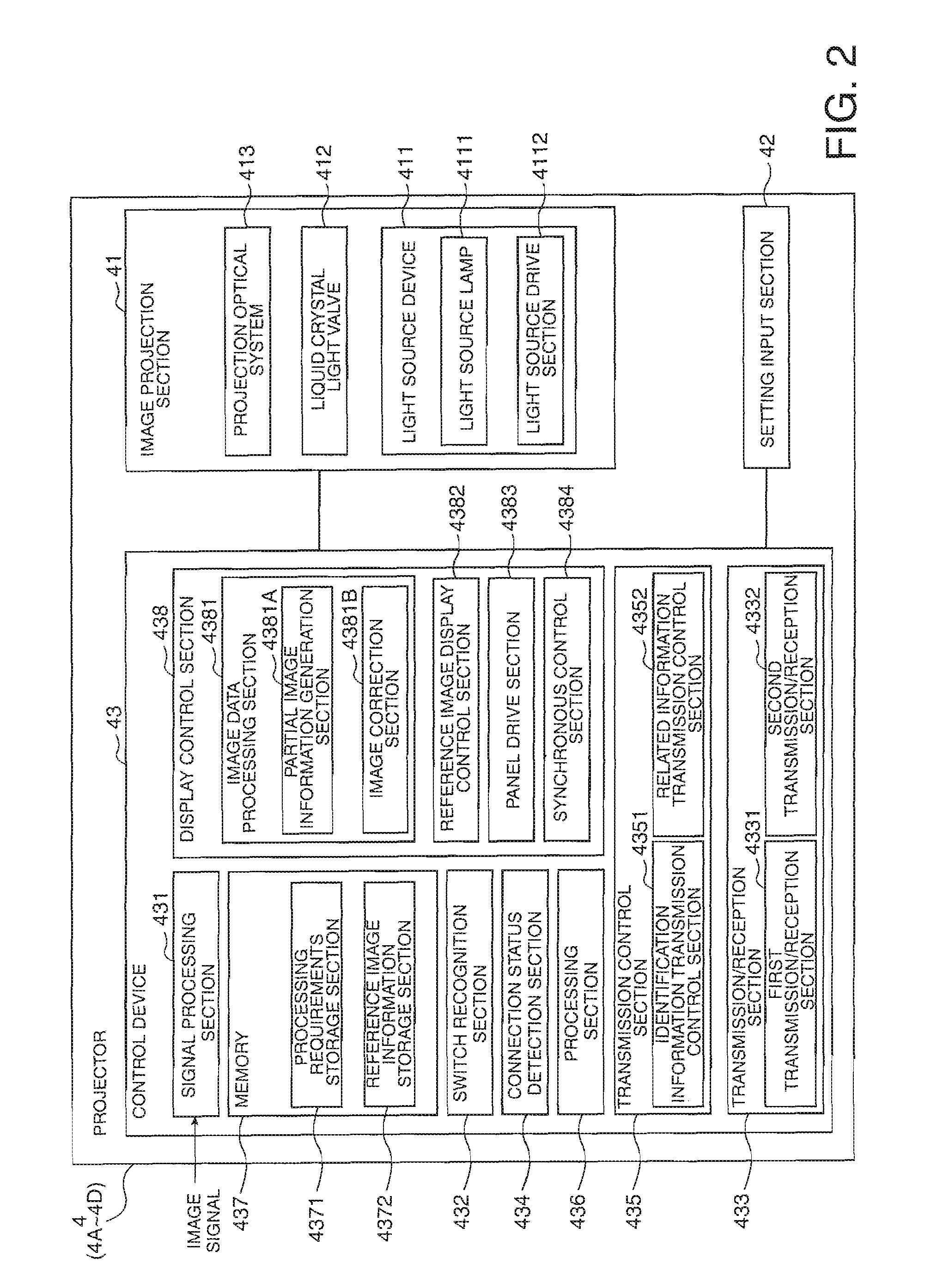
[0219]FIG. 10 is a block diagram showing the configuration of a projector 40 in the second embodiment.

[0220]The only difference of the second embodiment from the first embodiment is that the projector 40 applies an edge blending process to image data for brightness adjustment. In the second embodiment, four of the projectors 40, i.e., projectors 40A, 40B, 40C, and 40D, are provided similarly to the first embodiment, and the image data for edge blending process is the one corresponding to overlapped portions, i.e., portions where partial images are overlapped, in partial image data. That is, the difference lays in the function of the image data processing section 4381, i.e., image correction section 4381...

third embodiment

[0231]Described next is a third embodiment of the invention by referring to the accompanying drawings.

[0232]In the description below, any configuration or component similar to that in the first embodiment is provided with the same reference numeral, and not described in detail again.

[0233]FIG. 13 is a block diagram showing the configuration of a multi-display system 10 in the third embodiment. In FIG. 13, for convenience, some of the components are not shown i.e., the signal lines S6 to S8, the signal input / output terminals 431B and 431C of each of the projectors 4, and the setting input sections 42.

[0234]In the first embodiment, the multi-display system 1 uses the image signal splitter 3 to distribute an image signal from the image output device 2 to the projectors 4A to 4D.

[0235]In the third embodiment, on the other hand, as shown in FIG. 13, in the multi-display system 10, the projectors 4A to 4D are connected in series, i.e., cascaded, using signal lines S12 to S14, and an image...


PUM


Abstract

A display device includes: a transmission / reception section that transmits and receives information to / from any other display device connected thereto; a setting input section that enables setting of relative position information about a relative position between the display device and the other display device; and a control device that generates partial image information from original image information, and makes a display section to display thereon a partial image. The control device includes: a related information transmission control section that transmits position-sequence-related information related to the relative position information; a configuration position recognition section that recognizes an absolute position of the partial image in the original image that is supposed to be displayed by the display device; and a partial image information generation section that generates the partial image information by cutting out at least a part of image information from the original image information.

Description

BACKGROUND[0001]1. Technical Field[0002]The present invention relates to a display device, a multi-display system, and an image information generation method.[0003]2. Related Art[0004]A multi-display system (projection display system) of a previous type includes a plurality of display devices, e.g., projectors, each generate partial image information from any input original image information, and display a partial image based on the partial image information. The display devices then each display its own partial image so that an original image based on the original image information is displayed on a large-sized screen of the multi-display, system with high intensity and resolution. For example, refer to JP-A-2000-207247 (Patent Document 1).[0005]With the technology of patent document 1, when a multi-display system is placed, a cascade connection is established among a computer device (hereinafter, referred to as PC) and all of the projectors. With such a cascade connection, based o...

Claims


Application Information

Patent Timeline
Patent Type & Authority Applications(United States)
IPC IPC(8): G03B21/26G09G5/00
CPCG03B21/26
Inventor HASEGAWA, HIROSHI
Owner SEIKO EPSON CORP
Features
  • Generate Ideas
  • Intellectual Property
  • Life Sciences
  • Materials
  • Tech Scout
  • Unparalleled Data Quality
  • Higher Quality Content
  • 60% Fewer Hallucinations
Learn More