Day/night weapon sight assembly for use on weapon without change in eye relief

a technology of eye relief and weapon, applied in the field of optical sights, can solve the problems of large and heavy sight optics, inability to generally be used in combat conditions, and disadvantageous separate weapon sights

Inactive Publication Date: 2008-02-14
AMERICAN TECH NETWORK
View PDF11 Cites 6 Cited by
  • Summary
  • Abstract
  • Description
  • Claims
  • Application Information

AI Technical Summary

Benefits of technology

[0028] It is an object of the invention to provide a day / night weapon sight with eye relief that remains unchanged when the weapon is equipped with an image intensifier tube for shooting at nighttime. Another object of the invention is to provide the weapon sight of the aforementioned type where the image intensifier tube can be constantly maintained on the weapon and switched between the inoperative position in which it is offset from the optical axis of the sight and the operative position in which is it located behind the conventional tubular optical sight without changing the eye relief. It is still another object to provide the weapon sight of the aforementioned type that allows replacement of the IIT with attachment of another type, e.g., flashlight, camcorder, etc.

Problems solved by technology

Photoelectrons accelerated and focused by the IIT's field bombard the screen, thus causing it to luminesce.
One disadvantage to having separate daytime and nighttime sights is that the sights must be individually boresighted to the weapon whenever the sight is initially installed, and must be checked for boresight whenever the sight is reinstalled on the weapon.
This is not generally feasible under combat conditions.
Separate weapon sights are also disadvantageous because the sights must be interchanged for day or night use.
It is obvious that the use of two separate optical paths at the same time makes the sight optics large and heavy, which is a significant drawback for weapons, which are manually carried by the user.
Although this system is more reliable than the previous one, in general it entails the same disadvantages since it does not suggest any other new solutions of the problems inherent in the sight with two parallel and simultaneously working optical paths.
Although the U.S. Pat. No. 6,131,294 solves the problems of the earlier described devices by providing a single-path day / night vision optics, it is still possesses a number of significant disadvantages, which are the following.
Furthermore, the night-vision device, such as an image intensifier tube, is a very delicate optical instrument, which requires accurate handling after replacement.
Therefore the use of the device of U.S. Pat. No. 6,131,294 is unsuitable for combat field conditions.
When the night-vision insert has a temperature different from the temperature of the stationary part of the sight, insertion of the night-vision block may cause fogging of the sight optics, which can make the sight inoperative for a substantial period of time.
Another problem associated with the use of the insertable night-vision block consists in that each insertion and removal requires readjustment of the optical system for refocusing.
A disadvantage of this device consists in that in addition to an image-intensifier unit it requires the use of an auxiliary daytime coupling assembly, both of which must be attached to opposite arms of a pivotable lever.
The use of the auxiliary daytime coupling contributes to an increase in the weight of the sight.
Another disadvantage of the design described in the aforementioned patent is that switching between the daytime use and the nighttime use requires rotation of the aforementioned lever with the entire housing and with switchable optics respective to the sight housing.
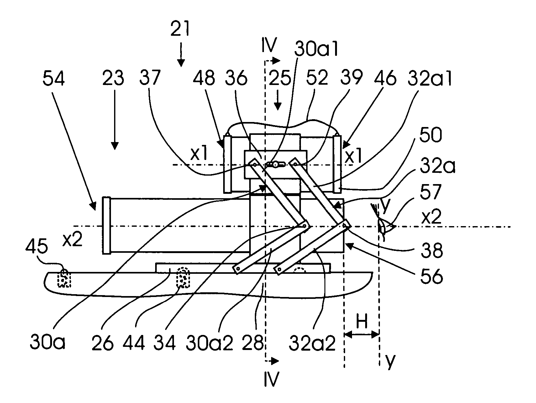
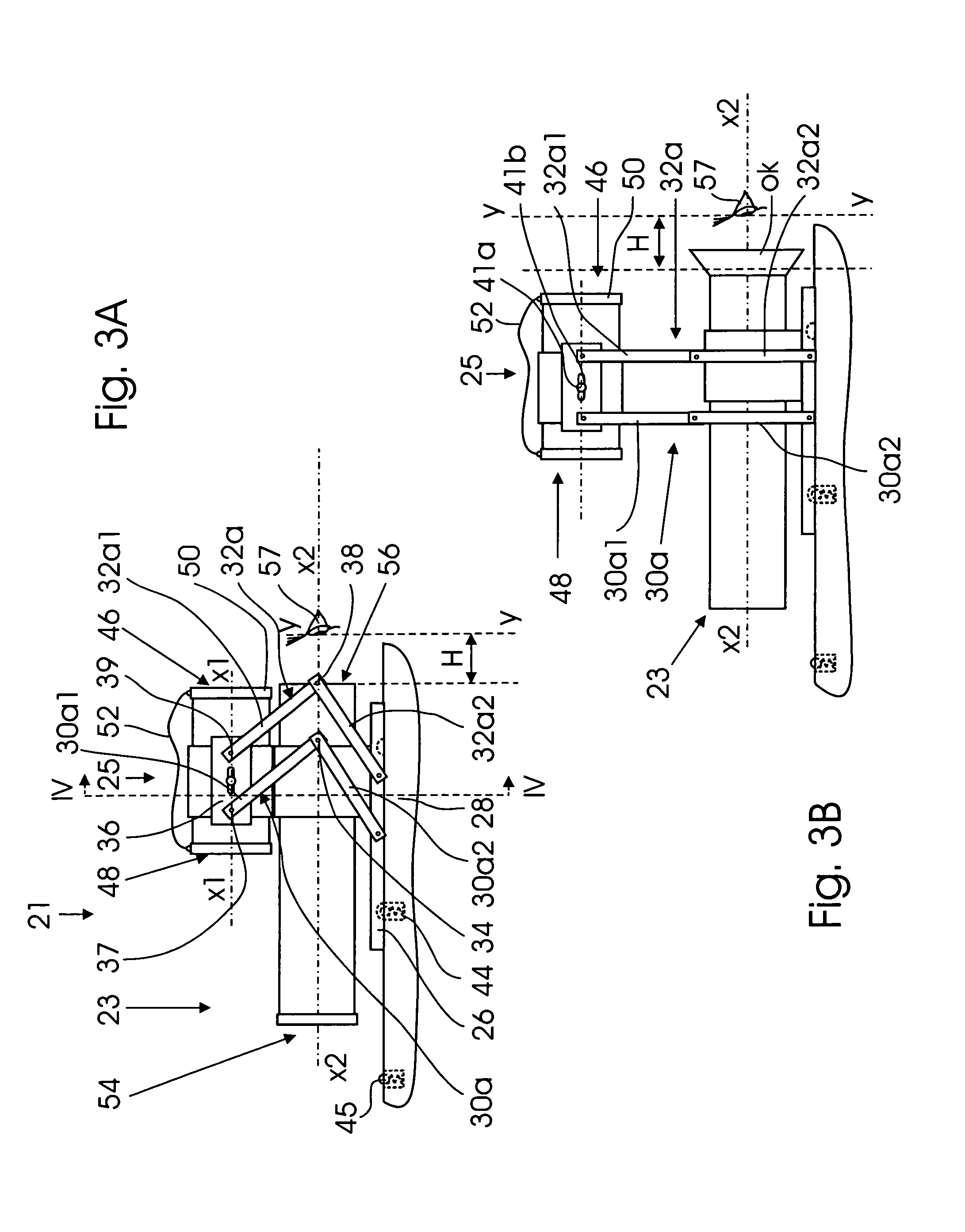
Another essential disadvantage of the sight disclosed by the aforementioned patent consists of the arrangement of rotatable optics for rotation in a plane perpendicular to the optical axis of the sight.
This leads to an increase in the vertical dimension of the sight.
A disadvantage of such an apparatus is that it is self-contained with the built-in image intensifier tube.
This means that the image intensifier tube cannot be separated and removed from the sight, e.g., for replacement with another image intensifier tube or an optical device of another type.
Nevertheless, all day / night sights for weapons described above and those known to the applicant, including those that contain removable IIT's or IIT's switchable between the operative and inoperative positions, have complicated and relatively expensive construction and significant weight and are not universal in the sense that in the majority of cases they are bound to weapons of specific models.
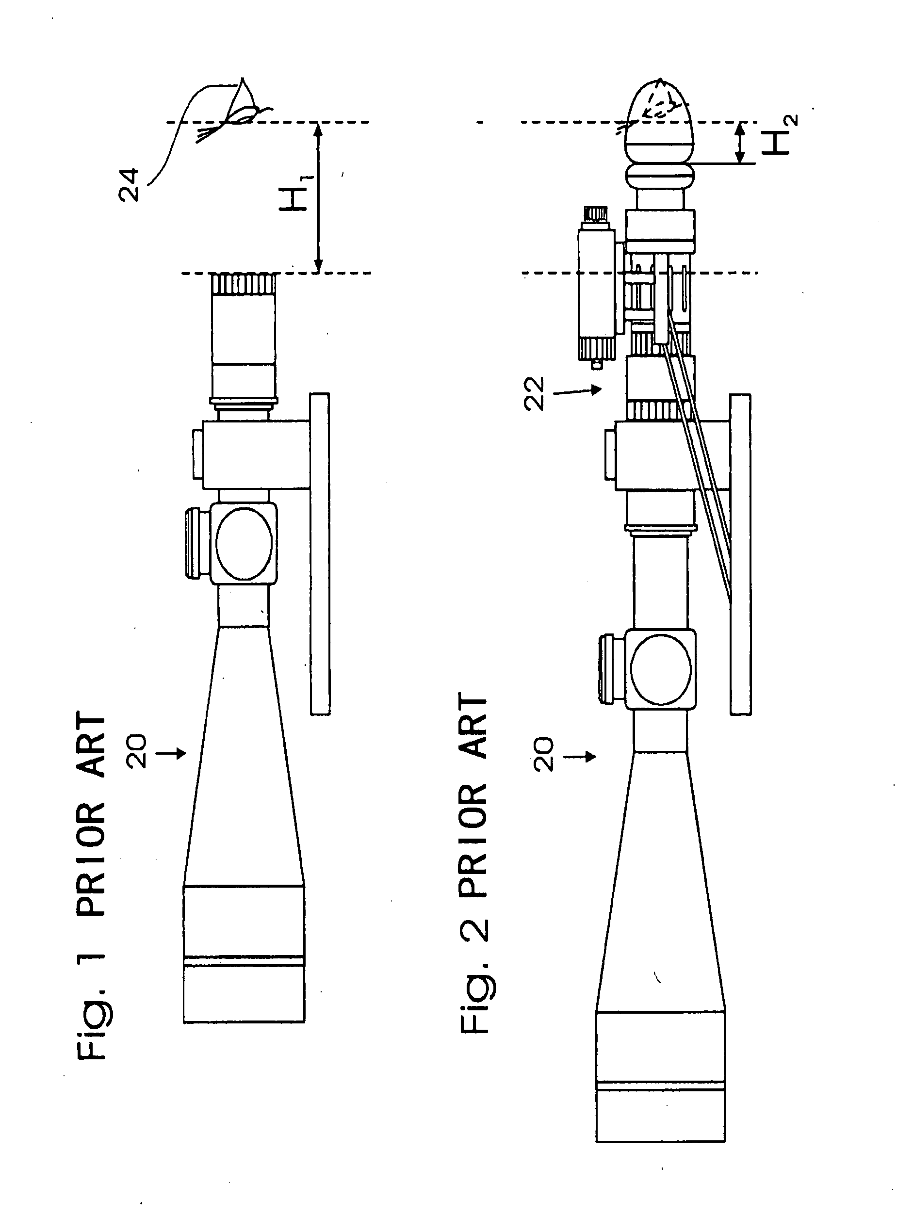
Although these advantages to some extent compensate for the necessity of frequent attaching / detaching operations, a serious disadvantage of the universal IIT of the above type is that it must be installed between the viewer eye and the ocular of the tubular optics, and this changes the eye-relief distance.
In other words, the IIT attached to the rear end of the conventional tubular optics significantly shortens the eye-relief distance to the extent that in some cases the recoil at the moment of shooting hits the user between the eyes.
In order to eliminate this problem, the user has to move the eye further away from the IIT's ocular, and in this case he / she cannot see the entire field of observation, and shooting conditions become inconvenient.
Therefore, the user has to move the weapon forward and cannot have normal conditions under which the weapon can rest on the user's shoulder.

Method used


Image

  • Day/night weapon sight assembly for use on weapon without change in eye relief
  • Day/night weapon sight assembly for use on weapon without change in eye relief
  • Day/night weapon sight assembly for use on weapon without change in eye relief

Examples


Embodiment Construction

[0034]FIG. 3A is a schematic side view of the optical sight assembly of the invention which, as a whole, is designated by reference numeral 21. The optical sight assembly 21 consists of a conventional optical sight tube 23 for daytime use and an image intensifier tube (IIT) 25. In the context of the present invention, the term “image intensifier tube” covers any other optical sight device, such as a spotting scope or the like. In FIG. 3A, the image intensifier tube 25 is shown in the inoperative position above the optical sight tube 23 with the optical axis X1-X1 of the IIT 25 arranged parallel to the optical axis X2-X2 of the optical sight tube 23. As can be seen in FIG. 3A, the optical sight tube 23 is attached to a sliding plate 26 that is guided on a receiver rail 28 that is rigidly attached to the rifle (not shown). The IIT 25 is supported by the sliding plate 26 with the use of a pair of double-member linking mechanisms 30a and 32a. It is understood that a pair of similar link...


PUM


Abstract

A day/night weapon sight assembly that consists of daytime sight and a nighttime sight allows the use of both sights without change in eye relief even when the nighttime sight is attached to the rear end of the daytime sight. This is achieved by supporting the daytime sight moveably in the direction of the optical axis and by supporting the nighttime sight with the use of a plane-parallel motion mechanism that allows switching of the nighttime sight between the upper inoperative position and the operative position behind and coaxially with the daytime sight.”

Description

FIELD OF THE INVENTION [0001] The present invention relates to optical sights, in particular to telescopic optical sights equipped with a switchable image intensifier tube, e.g., a night-vision spotting scope, which can be switched between an inoperative position for use of the telescopic optical sight tube, alone, and an operative position in which the optical sight tube can be used in combination with the telescopic sight for enhancing operation of the latter. More specifically, the invention relates to the day / night weapon sight assembly that allows switching of the image intensifier tube to an operative position behind the main telescopic optical sight without changes in eye-relief distance. BACKGROUND OF THE INVENTION [0002] There exists a great variety of optical sights of different types, in particular for installation on hunting, combat, or training weapons. In general a sight is utilized for aiming a weapon during daytime operation at a directly visible target and during ni...

Claims


Application Information

Patent Timeline
Patent Type & Authority Applications(United States)
IPC IPC(8): G02B23/12
CPCF41G1/32G02B23/12F41G11/001F41G1/387
Inventor GABER, LEONID
Owner AMERICAN TECH NETWORK
Why Eureka
Try Eureka