Inverter device and method for designing duty cycle setting section of inverter device

Inactive Publication Date: 2008-02-14
TOYOTA IND CORP
View PDF2 Cites 11 Cited by
  • Summary
  • Abstract
  • Description
  • Claims
  • Application Information

AI Technical Summary

Benefits of technology

[0007] Accordingly, it is an objective of the present invention to provide an inverter device that allows the effective value of output voltage to approximate to a theoretical value regardless of changes in input voltage, compared to the conventional art. It is another objective of the present invention to provide a method for designing a duty cycle setting section of an inverter device.

Problems solved by technology

However, since a conventional inverter device changes output voltage in proportion with fluctuation of input voltage, the effective value of the output voltage cannot be maintained constant.
However, in this case, prolonged time and increased cost are necessary for developing a software program, in accordance with which the duty cycle is determined.
However, in this case, the accuracy of the effective value of the output voltage of the inverter device becomes low.
That is, there is a large error between a target value and the design value of the effective value of the output voltage.

Method used


Image

  • Inverter device and method for designing duty cycle setting section of inverter device
  • Inverter device and method for designing duty cycle setting section of inverter device
  • Inverter device and method for designing duty cycle setting section of inverter device

Examples


first embodiment

[0020] FIGS. 1 to 8 illustrate the present invention.

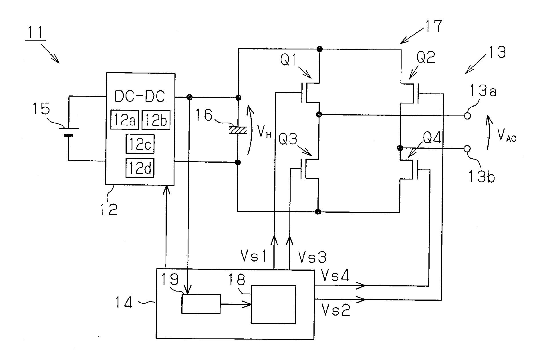
[0021]FIG. 1 represents an AC inverter 11, which is an inverter device according to the first embodiment. The AC inverter 11 is a DC / AC inverter device mounted in a vehicle. Referring to FIG. 1, the AC inverter 11 has a DC / DC converter section 12, a DC / AC inverter section 13, and a controller 14. A battery 15, or a DC voltage source, is mounted in the vehicle. The DC / DC converter section 12 steps up the voltage of the battery 15, which is, for example, DC 12 V, to DC voltage VH higher than the battery voltage. The DC / AC inverter section 13 converts the DC voltage VH into AC voltage Vac and outputs the AC voltage Vac to a pair of output terminals 13a, 13b. In this manner, the AC inverter 11 supplies the power of the battery 15 to load devices (not shown).

[0022] The DC / DC converter section 12 includes a pair of switching elements 12a, 12b, a step-up transformer 12c, and a rectifier circuit 12d. The controller 14 controls switching ...


PUM


Abstract

An inverter device has a DC / AC inverter section that converts input DC voltage into AC voltage with a rectangular wave and outputs the AC voltage. A duty cycle setting section sets a duty cycle for controlling turning on and off of a switching element of the DC-AC inverter section by a controller. The duty cycle setting section determines the duty cycle using a signal based on the value of the DC voltage and a charging curve determined by a CR circuit. Accordingly, regardless of changes in the input voltage, the effective value of the output voltage approximates to a theoretical value compared to the conventional art.

Description

CROSS-REFERENCE TO RELATED APPLICATIONS [0001] This application is based upon and claims the benefit of priority from the prior Japanese Patent Application Nos. 2006-218630, filed on Aug. 10, 2006, and 2007-167553, filed on Jun. 26, 2007, the entire contents of which are incorporated herein by reference. BACKGROUND OF THE INVENTION [0002] The present invention relates to an inverter device that outputs an AC voltage of a rectangular wave and a method for designing a duty cycle setting section of an inverter device. [0003] Some recent models of vehicles include an inverter device that converts voltage of a battery mounted in the vehicle into voltage used in home appliances, which is, for example, AC voltage of single-phase 100V or 120V. Such an inverter device, or a DC / AC inverter device, includes a DC / AC inverting circuit. However, since a conventional inverter device changes output voltage in proportion with fluctuation of input voltage, the effective value of the output voltage ca...

Claims


Application Information

Patent Timeline
IPC IPC(8): H02M7/537G06F17/10
CPCH02M2001/0022H02M7/48H02M1/0022
Inventor SUZUKI, SADANORITAKEUCHI, TAKASHITABATA, HIROTAKA
Owner TOYOTA IND CORP
Why Eureka
Try Eureka