Quenching Device for a Converter Bridge with Line Regeneration

a converter bridge and quenching device technology, applied in the direction of dynamo-electric converter control, emergency protective circuit arrangement, dc-ac conversion without reversal, etc., can solve the problem of line-commutated converters being the subject of shoot-through which occurs in feedback operation, further increase, and destruction of expensive thyristors or switches of such bridges. problem, to achieve the effect of simple arrangemen

Inactive Publication Date: 2008-02-14
SIEMENS AG
View PDF15 Cites 6 Cited by
  • Summary
  • Abstract
  • Description
  • Claims
  • Application Information

AI Technical Summary

Benefits of technology

[0011] In this way, solely by determining process variables (“output direct current”, “three-phase voltage”), which are required in any event for the normal function of the converter, criteria are derived on the basis of which the quenching device is activated. Determination of these criteria is thus relatively simple to arrange and leads to a reliable control of the quenching device.

Problems solved by technology

With line-commutated converters, as are described for example in AT 404 414 B written by the applicant, faults in the voltage or current waveform, especially overvoltages and / or commutation errors, lead to a destruction of the expensive thyristors or switches of such a bridge.
In more precise terms the basic problem which arises with said line-commutated converters is that of shoot-through which occurs in feedback operation.
In such cases an overcurrent arises on power outage and sufficient dc voltage, e.g. a corresponding armature voltage of the motor, which further increases and is also no longer able to be quenched by the converter itself.
If their secure function is to be guaranteed, additional highly-controllable chokes are necessary to restrict the rise in the current and the costs are accordingly considerable, quite apart from the problematic dimensioning and regular maintenance required for secure operation.
Other methods for direct thyristor quenching with quenching capacitors are also known, for example the quenching of only one of the two halves of the converter bridge with a capacitor, whereby the motor current still fully loads the valves of the second half of the bridge until the motor current is completely reduced to zero and thereby protection is not possible in all cases.
A similar method is the quenching of both bridge halves with two capacitors and with a voltage limitation in parallel to this in each case, which however allows overvoltages at the motor.
In addition the stated methods do not protect against an overvoltage in the event of a power outage if there is a transformer between network and converter bridge.

Method used


Image

  • Quenching Device for a Converter Bridge with Line Regeneration
  • Quenching Device for a Converter Bridge with Line Regeneration
  • Quenching Device for a Converter Bridge with Line Regeneration

Examples


Embodiment Construction

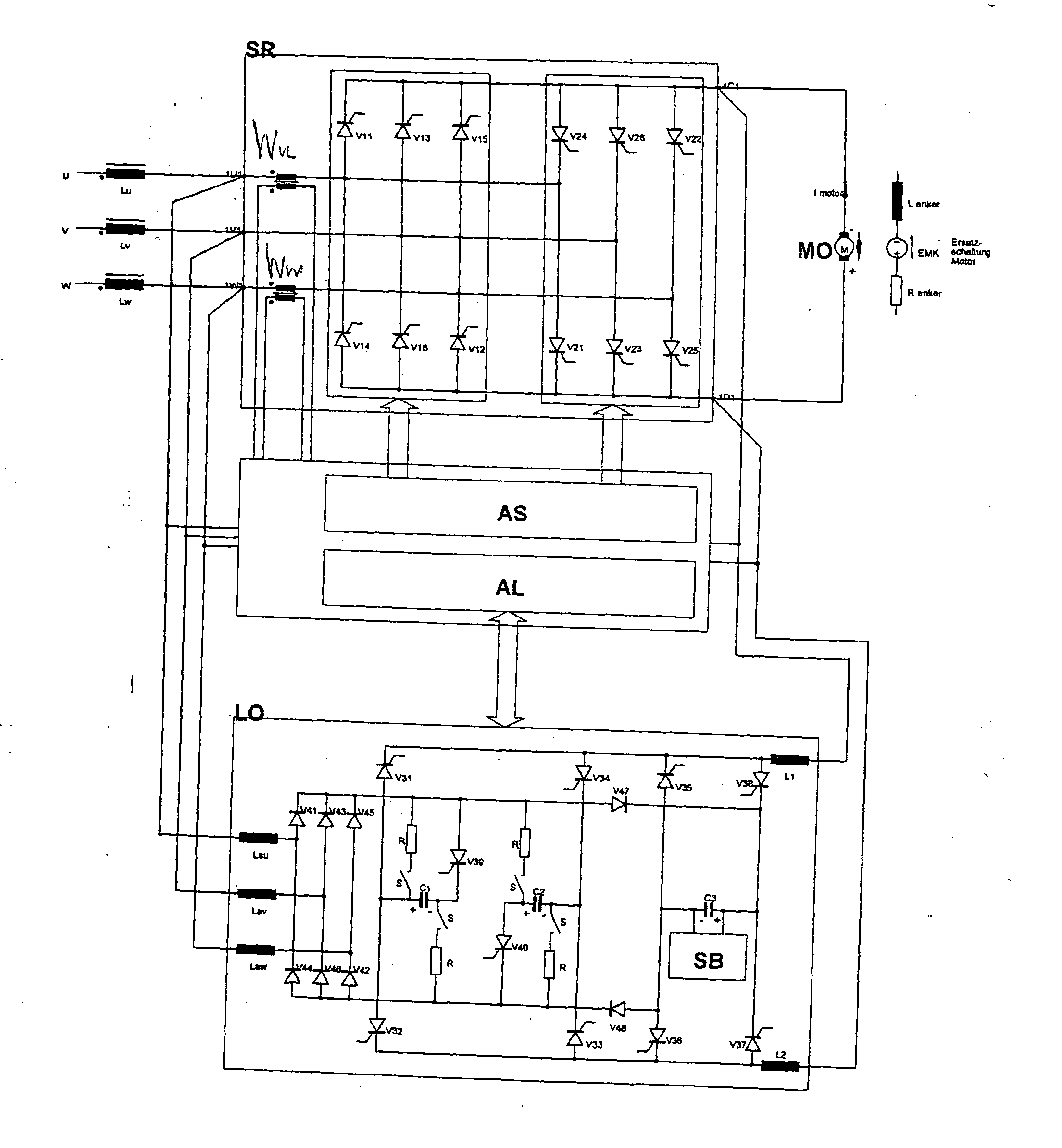
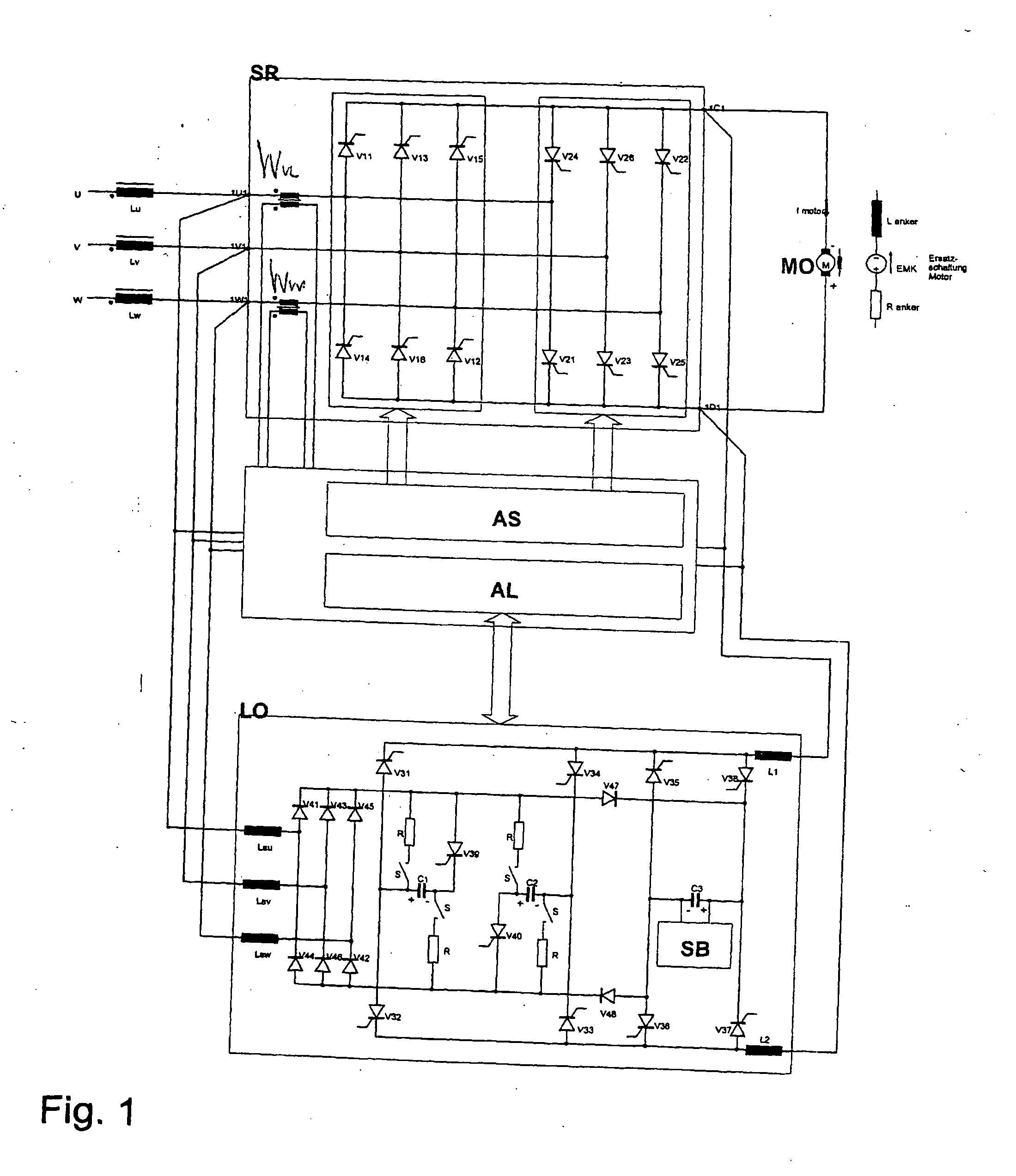
[0017] For a better understanding of the invention, FIG. 1 first shows a converter bridge triggered by a control circuit for supplying a direct current motor along with a typical quenching device with an associated trigger device. Such a quenching device is particularly well suited within the context of the invention, but basically other quenching devices can be used within the framework of the invention, which differ from the quenching device shown in some of their details which are not explained at any greater length here.

[0018] As can be seen from FIG. 1, the three phases U, V, W of a three-phase network are connected via commutation chokes Lu, Lv, Lw to the three-phase side of a converter bridge SRB. In this case a network fuse not shown in the drawing usually lies in each phase, as described for example in AT 404 414 B in conjunction with its FIG. 2. The controlled rectifier switches V11, . . . , V16 and V21, . . . , V26 are embodied as thyristors or comparable components.

[00...


PUM


Abstract

There is described a method for controlling a quenching device for a converter bridge with line regeneration, whereby the converter bridge controlled by a network-timed control circuit by ignition pulses is connected with its at least three inputs to the phases of a three-phase network and the at least two outputs of the bridge are connected to a direct-current motor which feeds, when operated as a generator, current back to the three-phase network via the bridge. The quenching device is controlled by a trigger unit which emits trigger pulses depending on the monitoring of electrical and temporary variables. The device has measuring values “direct output current” and/or “supply voltages” used to determine characteristic values which are compared with theoretical characteristic values. Depending on the result of said comparison, the quenching device is optionally activated.

Description

CROSS REFERENCE TO RELATED APPLICATIONS [0001] This application is the US National Stage of International Application No. PCT / EP2005 / 007493, filed Jul. 11, 2003 and claims the benefit thereof. The International Application claims the benefits of Austrian application No. A 1198 / 2004 filed Jul. 14, 2004, both of the applications are incorporated by reference herein in their entirety.FIELD OF INVENTION [0002] The invention relates to a method for controlling a quenching device for a converter bridge with line regeneration, whereby the converter bridge controlled by a network-timed control circuit by ignition pulses is connected with its three inputs to the phases of a three-phase network and the two outputs of the bridge are connected to a direct current motor, which feeds, when operated as a generator, current back to the three-phase network, and the quenching device is controlled by a trigger unit which emits trigger pulses depending on the monitoring of electrical and temporary vari...

Claims


Application Information

Patent Timeline
Patent Type & Authority Applications(United States)
IPC IPC(8): H02P7/28H02M5/25H02P7/292H02P7/295
CPCH02M1/32H02P7/281H02M7/155H02H7/12H02P7/28
Inventor BIRIBAUER, THOMASHACKL, FRANZHOFMULLER, WILFRIEDPICHORNER, HEINZRITSCHEL, WILHELMWOHRER, FRANZ
Owner SIEMENS AG
Why Eureka
Try Eureka