Novel bioreactor for generating uniform shear stress distribution

Inactive Publication Date: 2008-02-14
CHUNG CHENG INST TECH
View PDF3 Cites 15 Cited by
  • Summary
  • Abstract
  • Description
  • Claims
  • Application Information

AI Technical Summary

Benefits of technology

[0011]The main object of the present invention is to provide a bioreactor for generating uniform distribution of shear stress; wherein the uniformity of the distribution of shear stress acting on the dishes at the bottom is improved by changing the design of the cone shape, and not affected by the distance between the cone tip and the fixed plate.
[0012]Another object of the present invention is to provide a bioreactor for generating uniform distribution of sh

Problems solved by technology

However, the friction will occur when the cone is in the rotation mode with specific angular velocity and the cone tip and the fixed plate contact to each other, and this will result in some inaccuracy of the angular velocity of the cone.
The decrease of the rotating speed will cause the cells in the culture dish fail to experience the expected shear stress a

Method used


Image

  • Novel bioreactor for generating uniform shear stress distribution
  • Novel bioreactor for generating uniform shear stress distribution
  • Novel bioreactor for generating uniform shear stress distribution

Examples


example 1

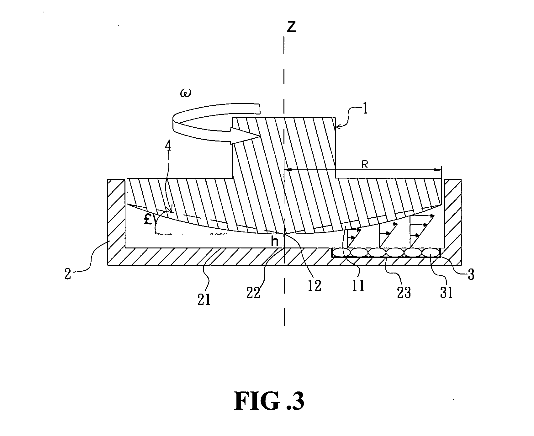
[0025]During the fabrication of the device of the present invention, the cone tip 12 of cone 1 having an outline of improved catenary with α=1° and C=0.643 (solid line) contacts with the center 22 of the fixed plate 21 first, and then raise the cone 1 up by 0.5 mm. After that, the shear stress is evaluated at 100 points evenly scattered in the circular area from r1=0.2 R to r2=0.9 R on the fixed plate 21. The value of shear stress acting on the fixed plate 21 from the cone of the present invention is compared with that from the traditional triangle cone 4 (dashed line) and subjected to statistical analysis. The standard deviation of shear stress reflects that the greater the standard deviation of shear stress is, the greater the fluctuation of shear stress is; which means that the distribution of shear stress is not uniform on the fixed plate 21. On the contrary, the smaller the standard deviation of shear stress is, the smaller the fluctuation of shear stress is; which means that t...

example 2

[0026]During the fabrication of the device of the present invention, the cone tip 12 of cone 1 having an outline of improved catenary with α=2° and C=0.495 (solid line) contacts with the center 22 of the fixed plate 21 first, and then raise the cone 1 up by 0.5 mm. After that, the shear stress is evaluated at 100 points evenly scattered in the circular area from r1=0.2 R to r2=0.9 R on the fixed plate 21. The value of shear stress acting on the fixed plate 21 from the cone of the present invention is compared with that from the traditional triangle cone 4 (dashed line) and subjected to statistical analysis. The standard deviation of shear stress reflects that the greater the standard deviation is, the greater the fluctuation of shear stress is; which means that the distribution of shear stress is not uniform on the fixed plate 21. In Table 2, it shows the standard deviations of shear stress generated by two different cones 1 and 4 at various rotating angular velocities (ω). It also ...

example 3

[0027]During the fabrication of the device of the present invention, the cone tip 12 of cone 1 having an outline of improved catenary with α=3° and C=0.429 (solid line) contacts with the center 22 of fixed plate 21 first, and then raise the cone 1 up by 0.5 mm. After that, the shear stress is evaluated at 100 points evenly scattered in the circular area from r1=0.2 R to r2=0.9 R on the fixed plate 21. The value of shear stress acting on the fixed plate 21 from the cone of the present invention is compared with that from the traditional triangle cone 4 (dashed line) and subjected to statistical analysis. In Table 3, it shows the standard deviations of the shear stress generated by two different cones 1 and 4 at various rotating angular velocities (ω). It also shows that the distribution of shear stress on the fixed plate 21 by using cone 1 is more uniform than that by using cone 4 despite the rotating angular velocity (ω).

TABLE 3h = 0.5 mm, α = 3°, C = 0.429ω = 1ω = 5ω = 10ω = 15Stan...


PUM


Abstract

The present invention relates to a bioreactor for generating uniform distribution of shear stress, comprising: a cone, having a cone surface with an outline of modified catenary; a container, having a fixed plate at the bottom inside the accommodating space of said container, and said fixed plate comprises a plurality of reservoirs; wherein the cone tip located above the center of said fixed plate is capable of loading culture media into the accommodating space of said container, that is, into the space between the cone surface and the fixed plate. More uniform shear stress can be generated in the culture media to act on the sample in the reservoirs of the fixed plate when the cone rotates and makes the culture media run. The bioreactor of the present invention can be applied to generate uniform shear stress acting on the fixed plate despite the distance between the cone tip and the fixed plate.

Description

BACKGROUND OF THE INVENTION[0001]1. Field of the Invention[0002]The present invention relates to a bioreactor for cell culturing, more particularly, to a device with cone-plate structure for cell culturing.[0003]2. Description of Related Art[0004]In general, the cell-culturing devices have been used to study the dynamic response of vascular endothelial cells to the shear stress from the fluid flow. Said cell-culturing devices mainly comprise a cone, a fixed plate and a culture dish placing on the fixed plate; wherein the cone top and a motor are connected to each other in order to drive the rotation of the cone. The distance h between the cone tip and the fixed plate is maintained at a very small value, and several round holes are made on the fixed plate to arrange the culture dishes in where the cells to be cultured can be evenly seeded. When the cells are cultured in the dishes, the height of the solution surface in the culture dishes is equal to the fixed plate surface. The liqui...

Claims


Application Information

Patent Timeline
IPC IPC(8): C12M3/00
CPCC12M23/10C12M35/04C12M25/14
Inventor TING, TA-WEICHEN, YU-LUN
Owner CHUNG CHENG INST TECH
Why Eureka
Try Eureka