X-ray tube and method to operate an x-ray tube

Inactive Publication Date: 2012-11-08
SIEMENS AG
View PDF6 Cites 4 Cited by
  • Summary
  • Abstract
  • Description
  • Claims
  • Application Information

AI Technical Summary

Benefits of technology

[0017]A thermal emitter is appropriately provided as an emission source of the cathode. The electrons are therefore emitted via heating of the cathode with a corresponding heating voltage. The emitted electron stream is dependent both on the heating voltage and on the area of the emitter. With the arrangement of the two quadrupole magnet systems with their focusing properties, the particular advantage is achieved that the emitter (thus the emitter area) can be chosen to be larger in comparison to conventional arrangements. The radius of the circular area of the emitter is advantageously greater than or equal to 4 mm. Typical radii are 3 mm, which (given the circular emitters) leads to an enlargement of the emitter area by nearly double. In operation, a lower heat power thus can be applied to achieve the same high emission current that is achieved otherwise with a higher heat power, so the lifespan of the emitter can be markedly extended. Conversely, at the same time higher emission currents given comparable or lower heating temperatures than are typical can also be achieved.
[0018]An additional, particular advantage of the focusing with the quadrupole doublet is that the focusing of the electron beam can be (and advantageously also is) conducted exclusively via this quadrupole doublet. Therefore, no additional focusing electrode (to which what is known as a grid o

Problems solved by technology

In general, in electron sources such as those in x-ray tubes, the electrons in the beam mutually influence each other, which can lead to a significant

Method used


Image

  • X-ray tube and method to operate an x-ray tube
  • X-ray tube and method to operate an x-ray tube
  • X-ray tube and method to operate an x-ray tube

Examples


Example

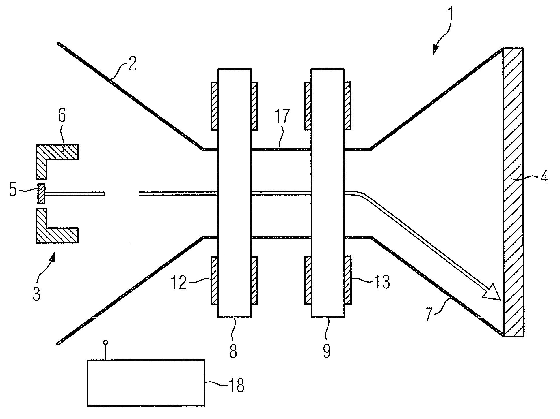
[0024]A rotary envelope x-ray radiator (also designated as an x-ray tube for short) that is designated as a whole with the reference character 1 has an evacuated housing 2 (which is also designated as a rotary envelope). The prior art cited above is referenced with regard to the principle function of the x-ray tube 1.

[0025]Arranged in the housing 2 are an electron source 3 on the one side and a disc-shaped anode 4 on the other side. The electron source 3 has a cathode 5 as an emitter and a focus head 6. The direction of the electron beam emanating from the cathode 5 is initially identical with the attenuation of the rotation axis of the housing 2. A drive device with which the housing 2 is set into rotation is not shown in FIG. 1.

[0026]The housing 2 has a funnel-shaped expansion pointing towards the anode 4, which has a significantly larger radial extent (relative to the rotation axis of the housing 2) in comparison to the electron source 3. In the region between the electron source...


PUM


Abstract

An x-ray tube has an evacuated, rotatable housing in which are arranged a cathode designed to emit an electron beam and an anode interacting with this cathode, and two quadrupole magnet systems arranged outside of the housing and spaced apart from one another that are provided to influence the electron beam.

Description

BACKGROUND OF THE INVENTION[0001]1. Field of the Invention[0002]The present invention concerns an x-ray tube of the type having an evacuated, rotatable housing in which are arranged a cathode designed to emit an electron beam and an anode interacting with the beam, with a quadrupole magnet system arranged outside of the housing to affect the electron beam. The invention furthermore concerns a method to operate such an x-ray tube.[0003]2. Description of the Prior Art[0004]A rotary impeller x-ray tube of the above type is known from DE 196 31 899 A1, for example. Individual coil elements of a quadrupole magnet system are arranged on a common support.[0005]Another x-ray tube with a quadrupole magnet system is known from DE 198 10 346 C1. In this case, in addition to the quadrupole magnet system, a coil spatially downstream of the quadrupole magnet system is provided with which the focal spot on the anode of the x-ray tube can be influenced.[0006]In general, in electron sources such as ...

Claims


Application Information

Patent Timeline
IPC IPC(8): H01J35/14
CPCH01J35/14H01J35/147
Inventor FERGER, THOMASFRITZLER, SVENMATUSZOK, DIETER
Owner SIEMENS AG
Why Eureka
Try Eureka