Movable Integrated Scanner for Surgical Imaging Applications

a surgical imaging and scanner technology, applied in the direction of geological measurements, reradiation, sensors, etc., can solve the problem that the pet does not provide any anatomical information

Active Publication Date: 2008-02-14
DEERFIELD IMAGING INC
View PDF8 Cites 26 Cited by
  • Summary
  • Abstract
  • Description
  • Claims
  • Application Information

AI Technical Summary

Benefits of technology

[0094] The integrated PET/MRI system can be suspended from the ceiling or mounted on a floor mounted bearing, with either system providing rotation of the magnet. The MRI system may also be suspended from the ceiling on rails, such that it can also be translated in space using the rail system. The rotational mechanism can either be located between the

Problems solved by technology

PET however does not provide any anatomical information, only

Method used


Image

  • Movable Integrated Scanner for Surgical Imaging Applications
  • Movable Integrated Scanner for Surgical Imaging Applications
  • Movable Integrated Scanner for Surgical Imaging Applications

Examples


Embodiment Construction

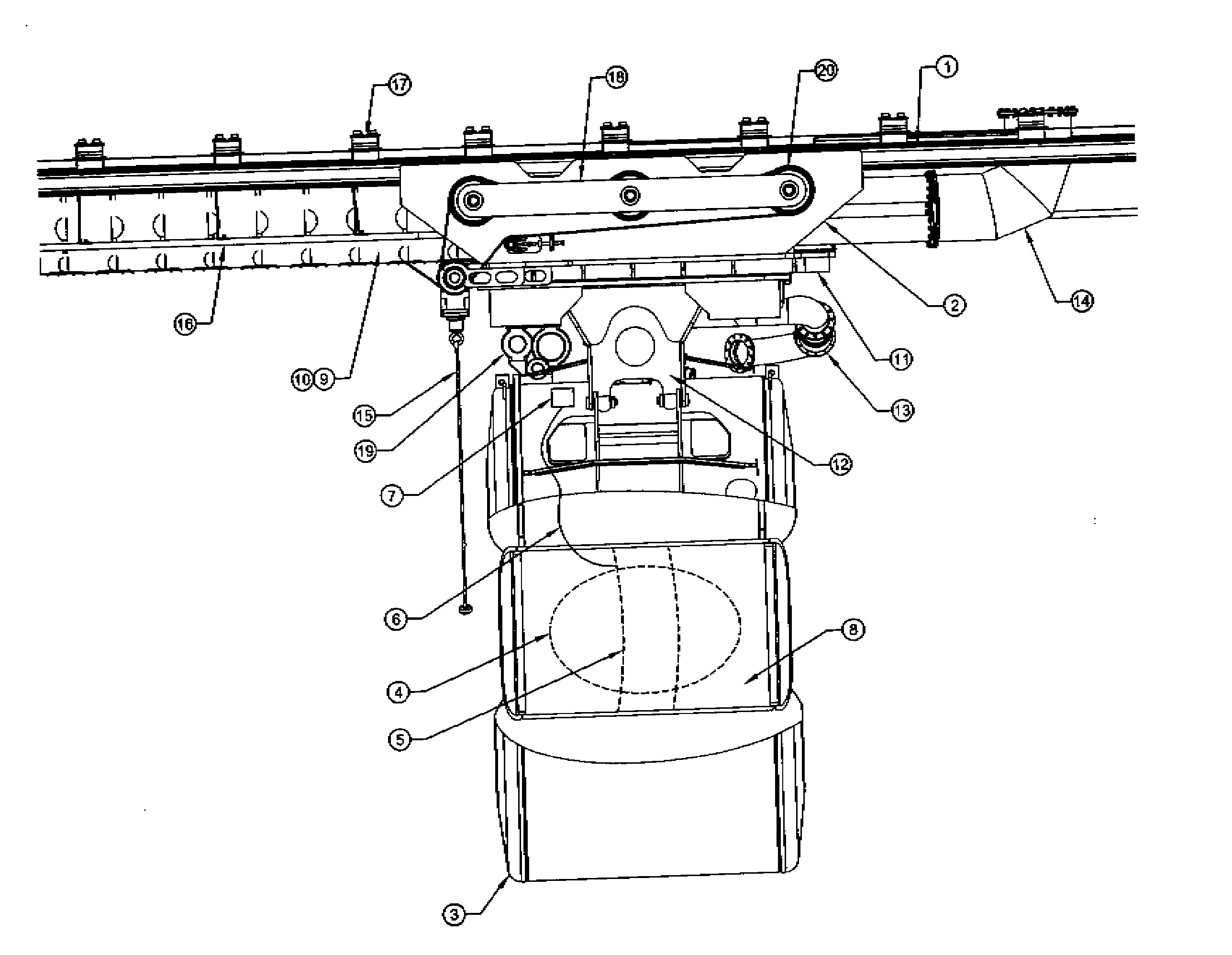
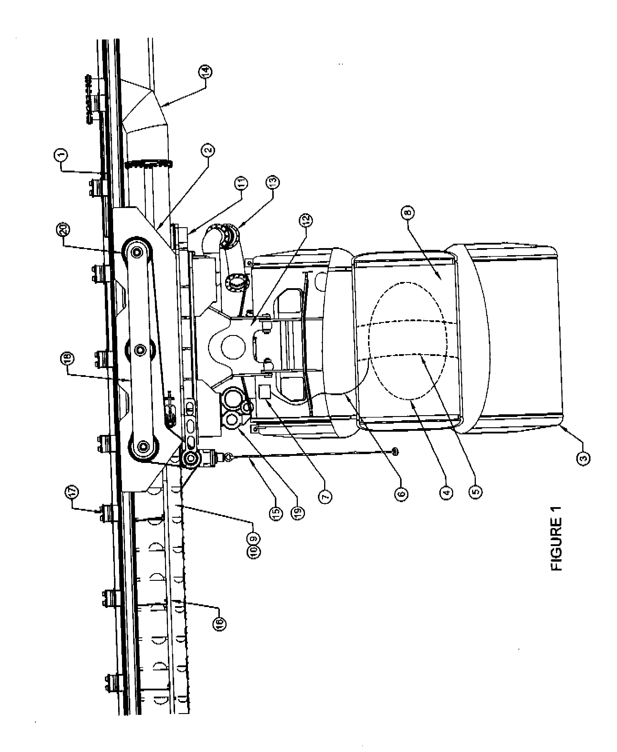
[0100]FIG. 1 shows the integrated PET / MRI scanner with rotating capacity. Ceiling rails 1 are bolted onto the structural steel of the building using Rail Clamps 17. Two ceiling rails are used, at a width apart approximately the same as the width of the magnet, although other widths are possible.

[0101] The magnet 3 is mounted onto the rails using a magnet Mover System 2. The upper part of the magnet Mover System traverses the rails, and does not rotate. The lower part of the magnet Mover System is connected to Slew Ring 11 so that it can rotate relative to the upper part. The Slew Ring 11 is motor driven, and carefully rotates the magnet system over a given angle, such as 90 degrees, 180 degrees or 270 degrees depending on the type of room layout being implemented. For both translational and rotational movements, the motor drive system can include gentle acceleration and deceleration in keeping with the requirements of the magnet system. The lower part of the magnet Mover System is ...


PUM


Abstract

A patient imaging system includes a patient support table, an MRI system including a cylindrical magnet and a PET system including positron detectors mounted in a ring. The magnet defines a cylindrical bore for receiving the patient on the table where the magnet is mounted for rotation about a vertical axis on a slew ring carried on rails allowing longitudinal movement. The PET ring is mounted in the bore for longitudinal movement. The quench tube for the magnet passes through the slew ring with a rotary union at the axis. The shielding covers include a fixed upper part and a lower part which rotates about the axis with the magnet. The magnet is arranged in a two or three room diagnostic configuration in which a holding bay houses the magnet and the diagnostic patients are organized in the three rooms each cooperating with the magnet bay as the magnet is rotated.

Description

[0001] This application claims the benefit under 35 USC 119 of the filing date of Provisional Application 60 / 805241 filed Jun. 20, 2006. [0002] This invention relates to a movable apparatus for obtaining medical scanned images of a patient. The apparatus may provide the possibility for combining and sequencing both PET and MRI detection capability for surgical imaging applications. The apparatus may provide movement in both translational and rotational directions to optimize the utility and effectiveness of the system.BACKGROUND OF THE INVENTION [0003] Both PET (Positron Emission Tomography) and MRI (Magnetic Resonance Imaging) are known techniques which can be used to image the body. In the case of PET, a solution is injected or taken into the body, the solution which contains molecules with positron emitting atoms. Therefore, once positron detector geometry is properly positioned around the patient, and once software is used to identify the location of the positron emission, the l...

Claims


Application Information

Patent Timeline
IPC IPC(8): A61B5/055
CPCG01R33/481A61B5/055A61B5/0035G01R33/28G01R33/38
Inventor GRAVES, DAVIDSAUNDERS, JOHNKLIMENKO, GORDLENTZ, TONYYU, HONGLI, JONATHANSCHELLENBERG, JAMES
Owner DEERFIELD IMAGING INC
Why Eureka
Try Eureka