Ophthalmic Drug Dispensing Tip

Inactive Publication Date: 2008-02-14
PINE JERROLD SCOTT
View PDF10 Cites 17 Cited by
  • Summary
  • Abstract
  • Description
  • Claims
  • Application Information

AI Technical Summary

Benefits of technology

[0017]It is another aspect of the present invention to provide a means to regulate drop flow and volume.
[0018]It is another aspect of

Problems solved by technology

In addition, this particular device may serve to prevent cross-contamination, and ultimately save both the patient and the healthcare system money typically lost t

Method used


Image

  • Ophthalmic Drug Dispensing Tip
  • Ophthalmic Drug Dispensing Tip
  • Ophthalmic Drug Dispensing Tip

Examples


Embodiment Construction

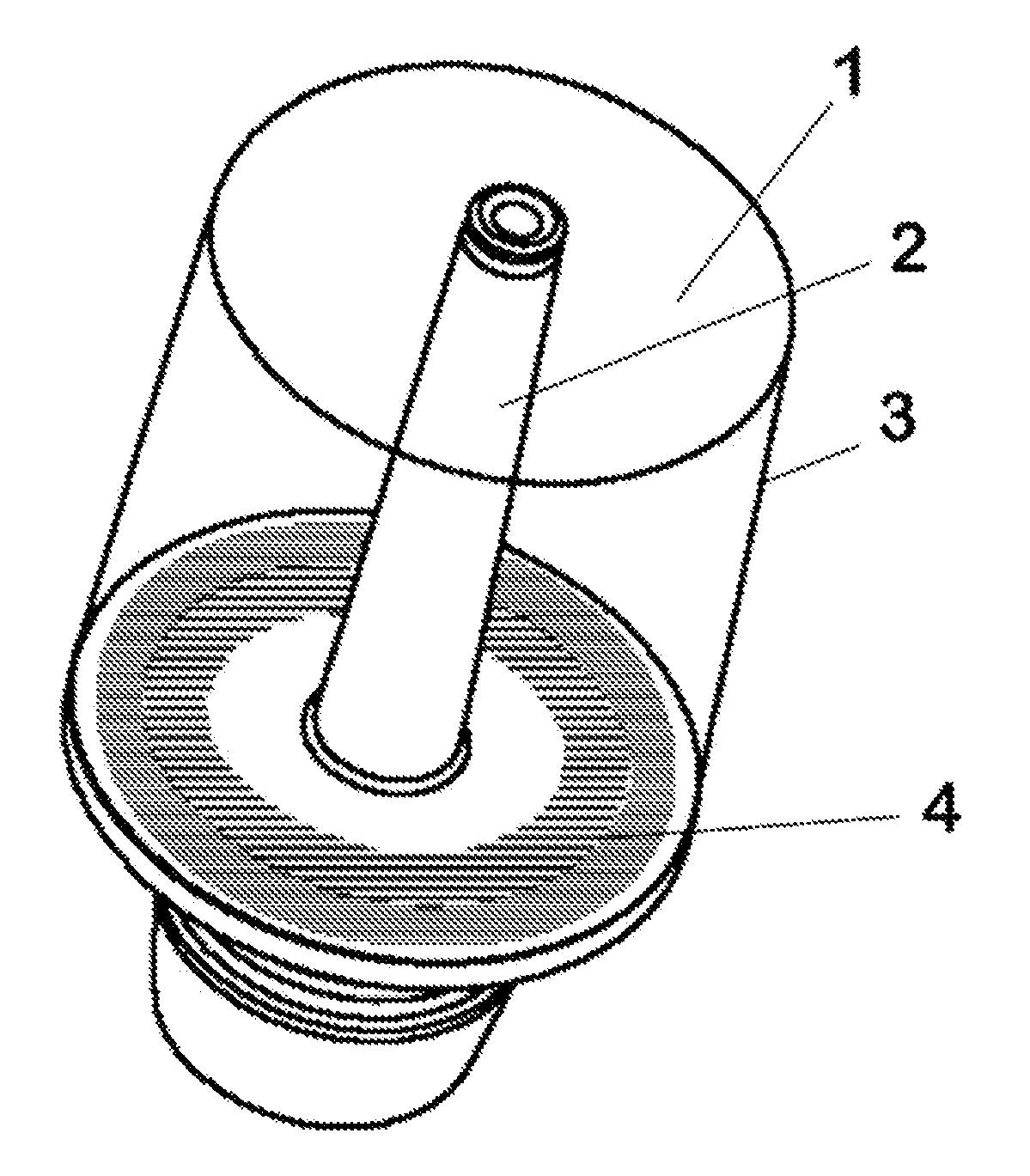
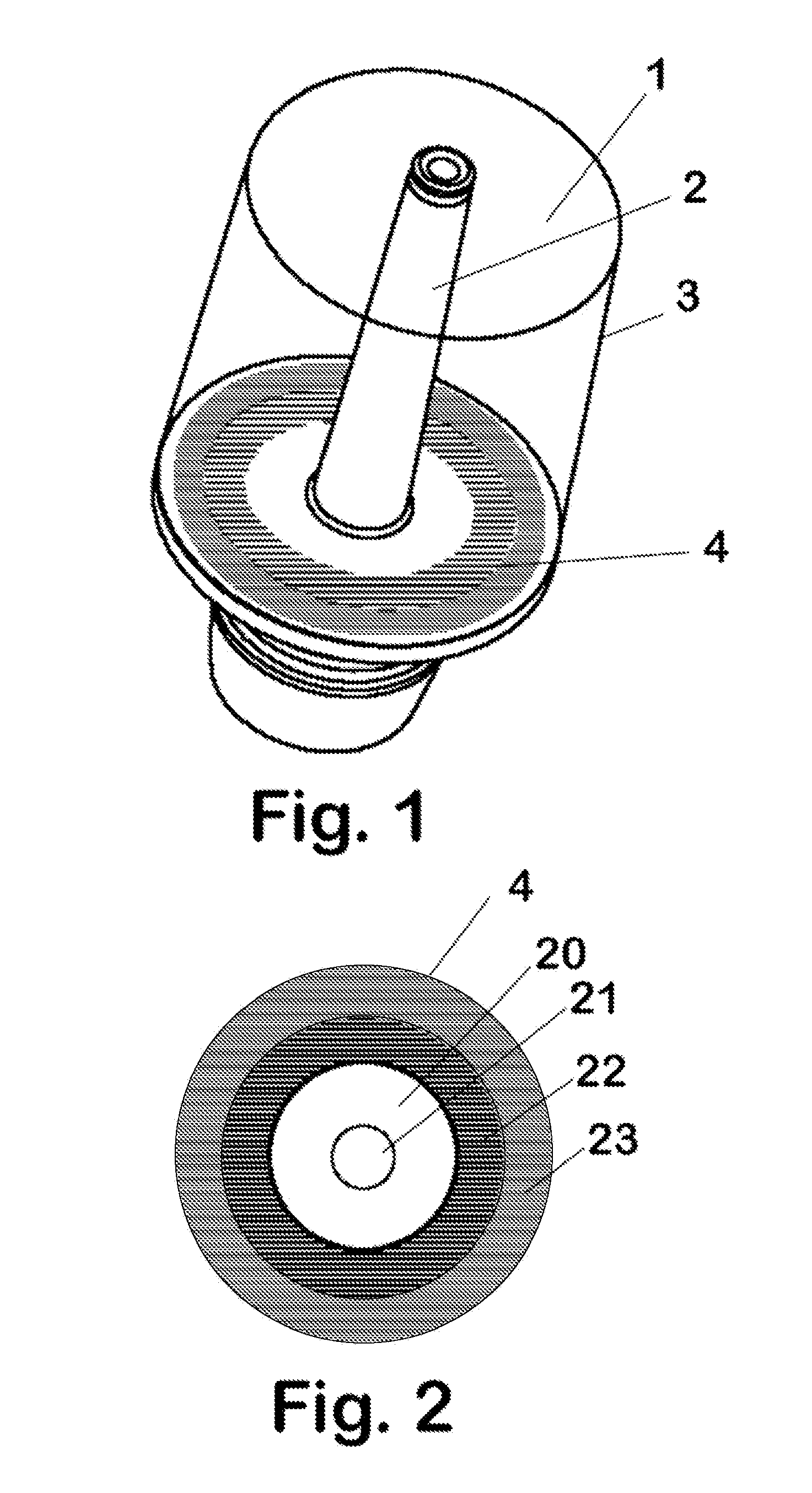
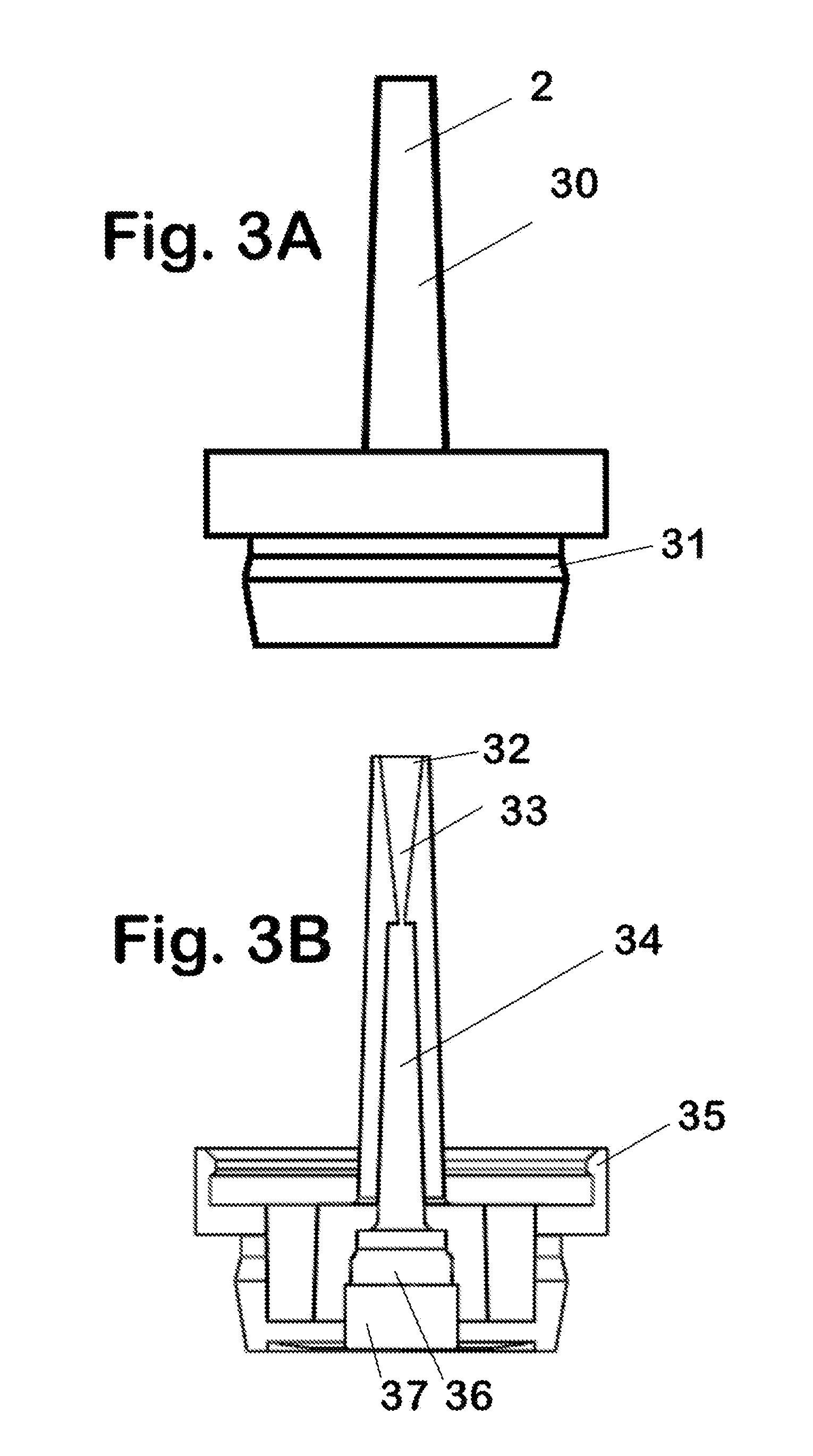
[0034]Referring to FIG. 1 an optical gauging dispensing tip assembly 1 in accordance with the present invention is illustrated. The optical gauging dispensing tip assembly 1 is comprised of three main components, a dispensing tip 2 for dispensing an ophthalmic solution, an integrated lens assembly 3 having an integrated housing as will be described below, and an optical target 4 calibrated for use as will be described below. The optical gauging dispensing tip assembly 1 is designed to give visual feedback to dispense an eye drop properly. The eye drop can be any ophthalmic solution comprising either an OTC medication or a prescription medication to treat various eye conditions. To effectively deliver an eye drop, the user needs feedback when the dispensing tip 2 is positioned at the center of the eye and sufficiently close to the eye to guarantee the drop is delivered to the eye. Another requirement is that the dispensing tip 2 does not contact the eye and contaminate the tip with o...


PUM


Abstract

A dispensing tip apparatus for an eye drop dispenser to administer topical ophthalmic solutions is described. The apparatus integrates an ophthalmic solution-dispensing tip with an optical gauging assembly. The tip provides continuous visual feedback about it orientation and relationship to the eye. The dispensing tip when attached to any standard topical ophthalmic solution dispensing bottle or reservoir enables the user to view a target, visually align the dispenser tip, and administer an eye drop with precision. There is also a visual feedback by which the dispenser tip is prevented from gaining too close proximity and contacting the eye, thus preventing contamination of the medication and its dispenser. The visual feedback can also contain textual or graphic information that serves as a promotional advertisement.

Description

BACKGROUND OF THE INVENTION[0001]According to clinical studies a staggering 37.6% of all self-administered eye drops miss the eye. One way to improve delivery of eye drops is by providing a visual feedback means so that a person dispensing drops can position an eye drop dispenser at an optimal distance and orientation above the eye. To accomplish visual feedback, the eyedropper needs to incorporate features used in other visual range and orientation devices. One such device is a common range finder used by golfers to gauge their distance from the ball to the hole. In golf range finders, the golfer stands near their ball and looks through a lens directly at the flag on its pole. The flags are uniform at a fixed height above the ground. The closer a golfer is to the flag, the larger it appears in the range finder. The range finder has calibrated hash marks within that correspond to a given distance. The golfer by aligning the appropriate hash mark with the image of the flagpole gets d...

Claims


Application Information

Patent Timeline
IPC IPC(8): A61M35/00
CPCA61F9/0008
Inventor PINE, JERROLD SCOTT
Owner PINE JERROLD SCOTT
Why Eureka
Try Eureka