
Method and system for grouping tracks for destaging on raid arrays

a raid array and track technology, applied in the field of data storage systems, can solve the problems of partial stripe writes, latency of completing standard write operations across multiple disks, and write penalty (or latency) for maximizing full stripe writes, and achieve the effect of reducing the write penalty or latency

Inactive Publication Date: 2008-02-14
IBM CORP
View PDF4 Cites 80 Cited by
  • Summary
  • Abstract
  • Description
  • Claims
  • Application Information

AI Technical Summary

Benefits of technology

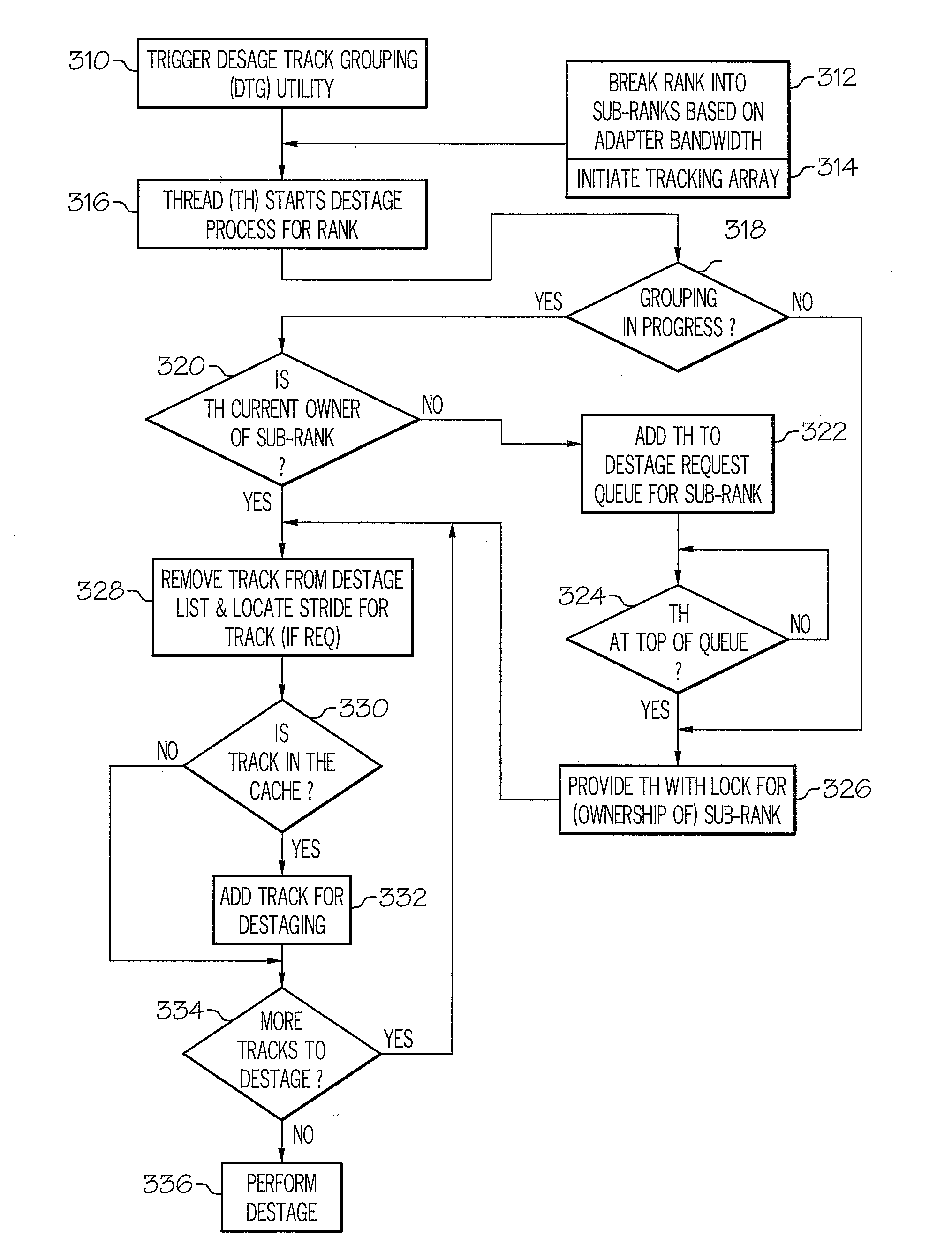
[0013]Disclosed is a method, system and processor for substantially reducing the write penalty (or latency) associated with writes and / or destaging operations within a RAID 5 array and / or RAID 6 array. When a write or destaging operation is initiated, i.e., when modified data is to be evicted from the cache, an existing data selection mechanism first selects the particular block of data to be evicted from the cache. The data selection mechanism then triggers a data track grouping (DTG) utility, which executes a thread to group data tracks, in order to maximize full stripe writes.
[0014]The DTG utility implements a sequence of processes to attempt to construct full stripes from the data sets, based on the data track selected for eviction. Once the DTG algorithm completes the grouping of all data tracks that complete a full stripe, a full-stripe write is performed, and parity is generated without requiring a read from the disk. In this manner, the write penalty is substantially reduced, and the overall write performance of the processor is significantly improved.

Problems solved by technology

One drawback of the various RAID levels is the latency involved in completing standard write operations across multiple disks.
One of the drawbacks of the above two methods is that both methods are completed after the data set for a write is determined, resulting in partial-stripe writes and the associated latency.

Method used


Image

  • Method and system for grouping tracks for destaging on raid arrays
  • Method and system for grouping tracks for destaging on raid arrays
  • Method and system for grouping tracks for destaging on raid arrays

Examples


Embodiment Construction

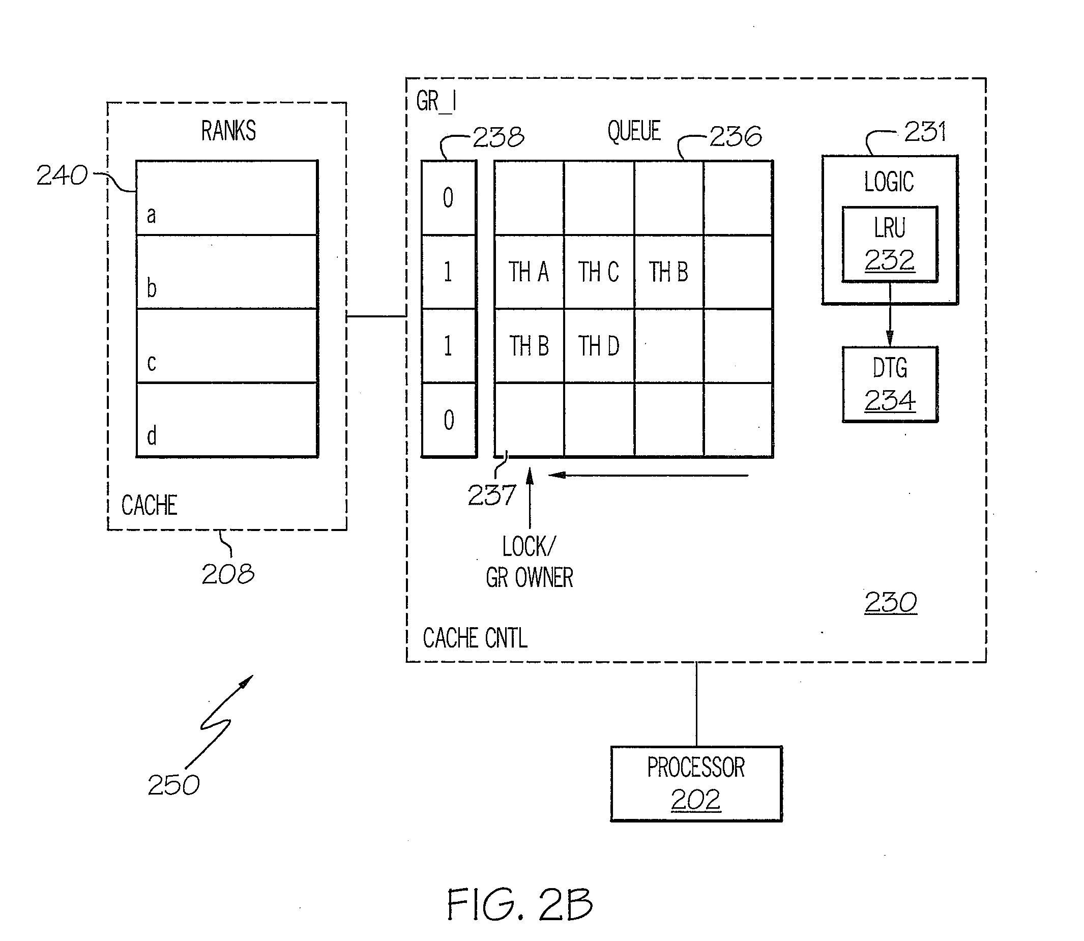
[0022]The present invention provides a method, system and processor for substantially reducing the write penalty (or latency) associated with writes and / or destaging operations within a RAID 5 array and / or RAID 6 array. When a write or destaging operation is initiated, i.e., when modified data is to be evicted from the cache, an existing data selection mechanism first selects the track of data to be evicted from the cache. The data selection mechanism then triggers a data track grouping (DTG) utility, which executes a thread to group data tracks, in order to maximize full stripe writes. Once the DTG algorithm completes the grouping of data tracks to complete a full stripe, a full-stripe write is performed, and parity is generated without requiring a read from the disk(s). In this manner, the write penalty is substantially reduced, and the overall write performance of the processor is significantly improved.

[0023]In one embodiment, each rank within the cache is broken into sub-ranks,...


PUM


Abstract

A method, system and processor for substantially reducing the write penalty (or latency) associated with writes and / or destaging operations within a RAID 5 array and / or RAID 6 array. When a write or destaging operation is initiated, i.e., when modified data is to be evicted from the cache, an existing data selection mechanism first selects the track of data to be evicted from the cache. The data selection mechanism then triggers a data track grouping (DTG) utility, which executes a thread to group data tracks, in order to maximize full stripe writes. Once the DTG algorithm completes the grouping of data tracks to complete a full stripe, a fall-stripe write is performed, and parity is generated without requiring a read from the disk(s). In this manner, the write penalty is substantially reduced, and the overall write performance of the processor is significantly improved.

Description

BACKGROUND OF THE INVENTION[0001]1. Technical Field[0002]The present invention generally relates to data storage systems, and in particular to Redundant Array of Independent Disks (RAID) data storage systems. Still more particularly, the present invention relates to efficiently handling write and / or destaging operations on RAID data storage systems.[0003]2. Description of the Related Art[0004]Conventional data processing systems perform memory access operations in a particular manner, based on the type of memory storage that is supported within the system. Typically, these memory storage are provided as a Redundant Array of Independent Disks (RAID).[0005]RAID is a disk subsystem that is used to increase performance and / or provide fault tolerance for data storage operations. RAID is a set of two or more ordinary hard disks and a specialized disk controller that contains RAID functionality. RAID improves performance by disk striping, which interleaves bytes or groups of bytes across m...

Claims


Application Information

Patent Timeline
Patent Type & Authority Applications(United States)
IPC IPC(8): G06F13/00
CPCG06F11/1076G06F12/0804G06F12/0866G06F11/108G06F2211/1009G06F2211/1057G06F2211/1059
Inventor ASH, KEVIN J.GUPTA, LOKESH M.JARVIS, THOMAS C.LOWE, STEVEN R.
Owner IBM CORP
Learn More