Method of Determining Abnormality in Particulate Filter

a technology of particulate filter and abnormality, which is applied in the direction of electrical control, machine/engine, separation process, etc., can solve the problems of deteriorating sensor detection accuracy, difficult to distinguish abnormalities from those caused, and difficult to detect minor abnormalities, etc., to achieve the effect of easy abnormality determination and short tim

Inactive Publication Date: 2008-02-21
TOYOTA JIDOSHA KK
View PDF18 Cites 75 Cited by
  • Summary
  • Abstract
  • Description
  • Claims
  • Application Information

AI Technical Summary

Benefits of technology

[0057] With such an abnormality determination method, it is possible to perform abnormality determination easily, in a short time.

Problems solved by technology

When a minor abnormality in which a small amount of PM is allowed to pass through a filter occurs in the filter, the exhaust gas pressure in the upstream of the filter and the pressure difference between the upstream and the downstream of the filter will change slightly, but it is difficult to distinguish such changes from those caused by changes in the amount of the PM trapped in the filter.
Therefore, it is difficult to detect a minor abnormality in a filter by the methods disclosed in Japanese Patent Publication No. 3-38406, Japanese Patent Application Laid-Open No. 6-323127, Japanese Patent Application Laid-Open No. 6-123216, Japanese Patent Application Laid-Open No. 6-330730, Japanese Patent Application Laid-Open No. 7-180528 and Japanese Patent Application Laid-Open No. 2001-207828.
In addition, in the case in which a reflectometer or a sound sensor is provided in the downstream of a filter or in a filter, there is a risk that accuracy of detection by the sensors can be deteriorated by soot adhering to them or by high temperature environment condition under which they are used.
Accordingly, it is sometimes difficult for the methods disclosed in Japanese Patent Application Laid-Open No. 5-98941 and Japanese Patent Application Laid-Open No. 8-121150 to detect a minor abnormality in the filter.

Method used


Image

  • Method of Determining Abnormality in Particulate Filter
  • Method of Determining Abnormality in Particulate Filter
  • Method of Determining Abnormality in Particulate Filter

Examples


embodiment 1

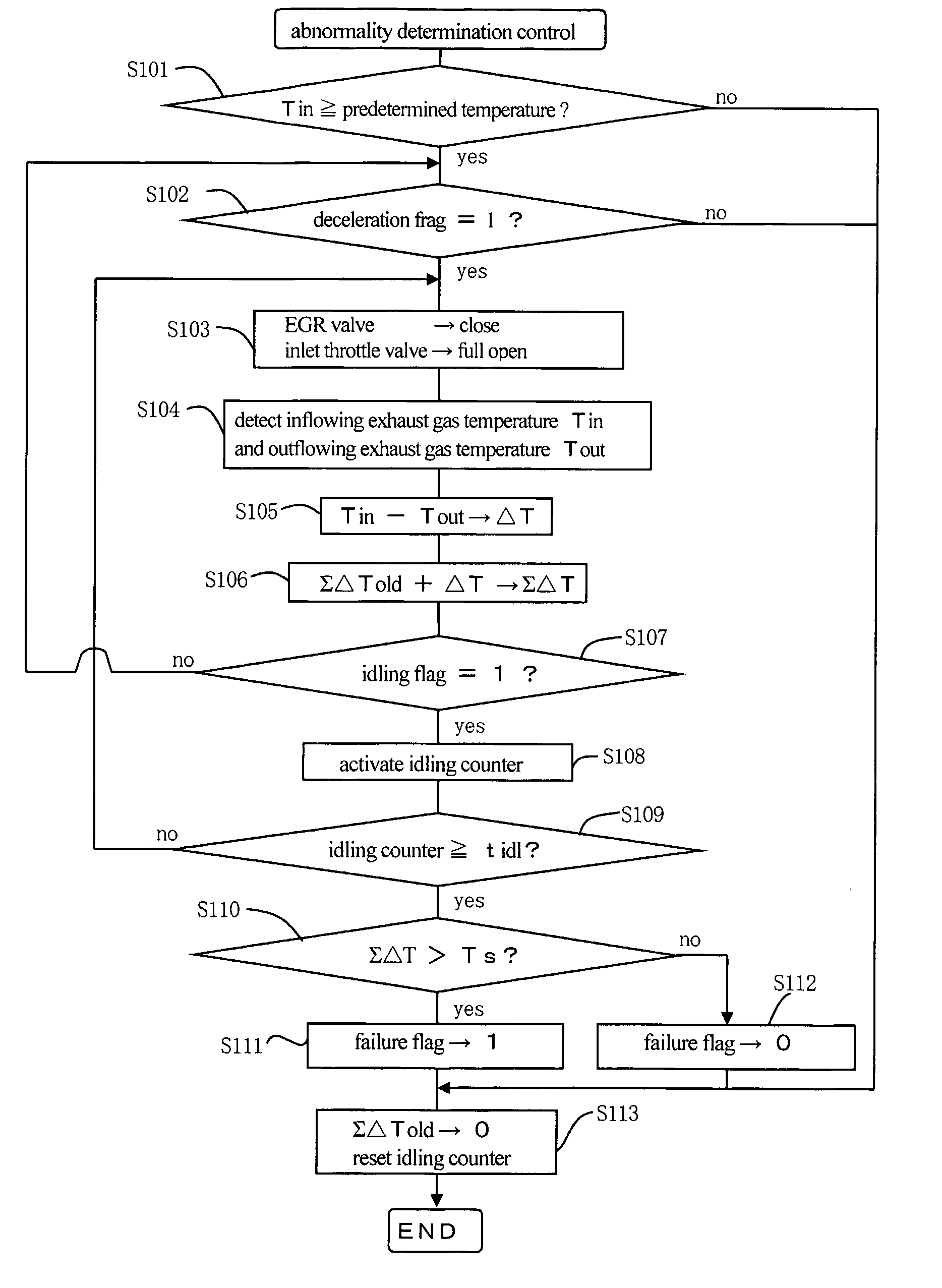
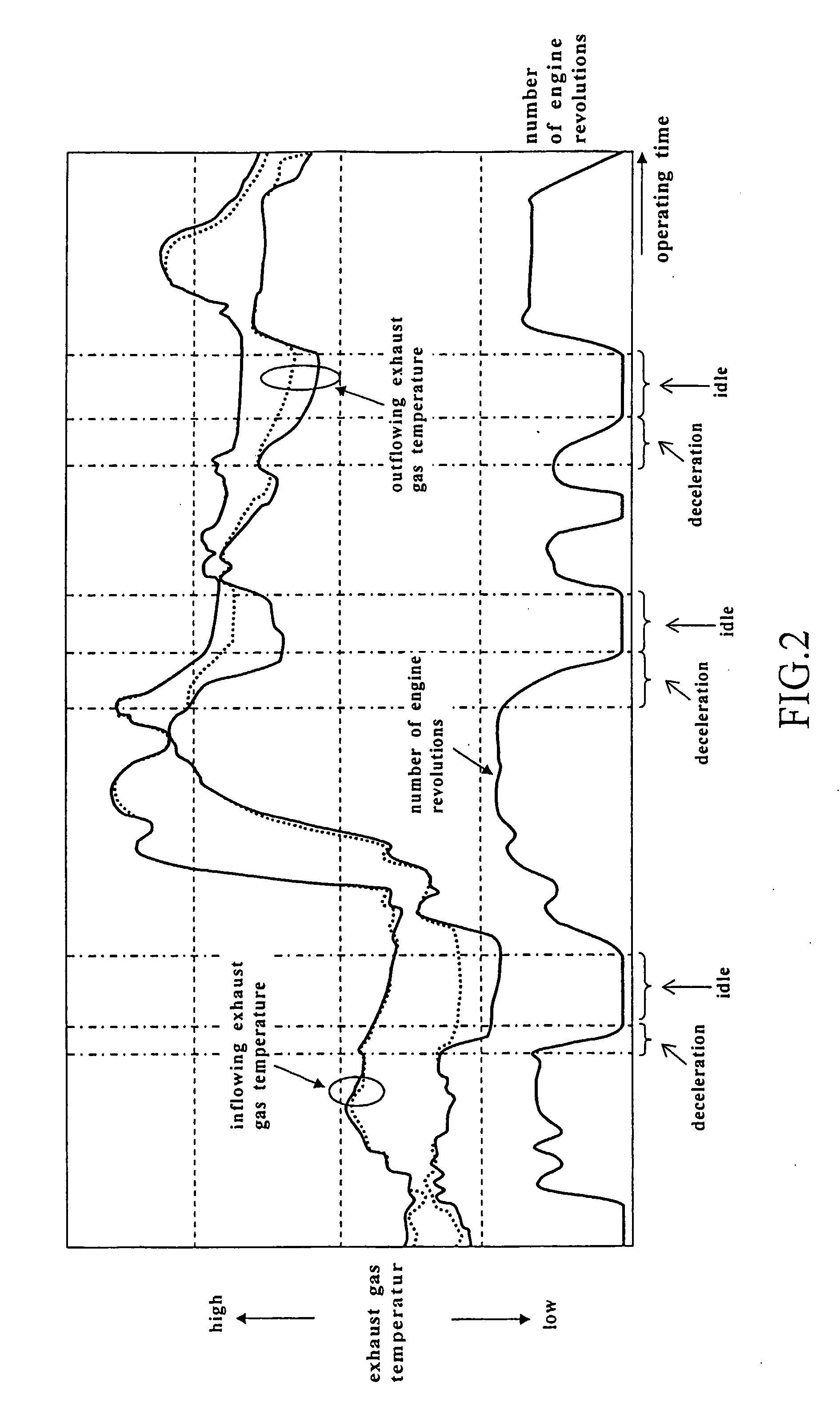
[0097] Firstly, a description will be directed to a case in which an abnormality in a particulate filter 5 is determined based on a relative relationship between the inflowing exhaust gas temperature and the outflowing exhaust gas temperature during the deceleration idling period.

[0098] As described before, the relative relationship between the amount of decrease in the inflowing exhaust gas temperature and the amount of decrease in the outflowing exhaust gas temperature during the deceleration idling period differs between in the case where the particulate filter 5 is normal and in the case where the particulate filter 5 is abnormal.

[0099] In the case where the particulate filter 5 is normal, the inflowing exhaust gas temperature decreases in the deceleration idling period, but the outflowing exhaust gas temperature is unlikely to change in this period. In other words, the decrease in the outflowing exhaust gas temperature relative to the decrease in the inflowing exhaust gas tem...

embodiment 2

[0129] Next, a case in which an abnormality in a particulate filter 5 is determined based on the degree of decrease in the outflowing exhaust gas temperature during a deceleration idling period will be described.

[0130]FIG. 6 is a graph showing behavior of the outflowing exhaust gas temperature during a deceleration idling period. In FIG. 6, the broken line represents the outflowing exhaust gas temperature in a case in which the particulate filter 5 is normal, and the solid line represents the outflowing exhaust gas temperature in a case in which the particulate filter 5 is abnormal.

[0131] In the case in which the particulate filter 5 is normal, the decrease amount of the outflowing exhaust gas temperature during the deceleration idling period is small. In contrast, in the case in which the particulate filter 5 is abnormal, the decrease amount of the outflowing exhaust gas temperature during the deceleration idling period becomes large. In other words, the decrease amount of the ou...

embodiment 3

[0154] Next, a case in which the outflowing exhaust gas temperature at the end of the deceleration idling period is estimated by computation and an abnormality in the particulate filter 5 is determined based on the difference between the estimated value and a value obtained by actual measurement will be described.

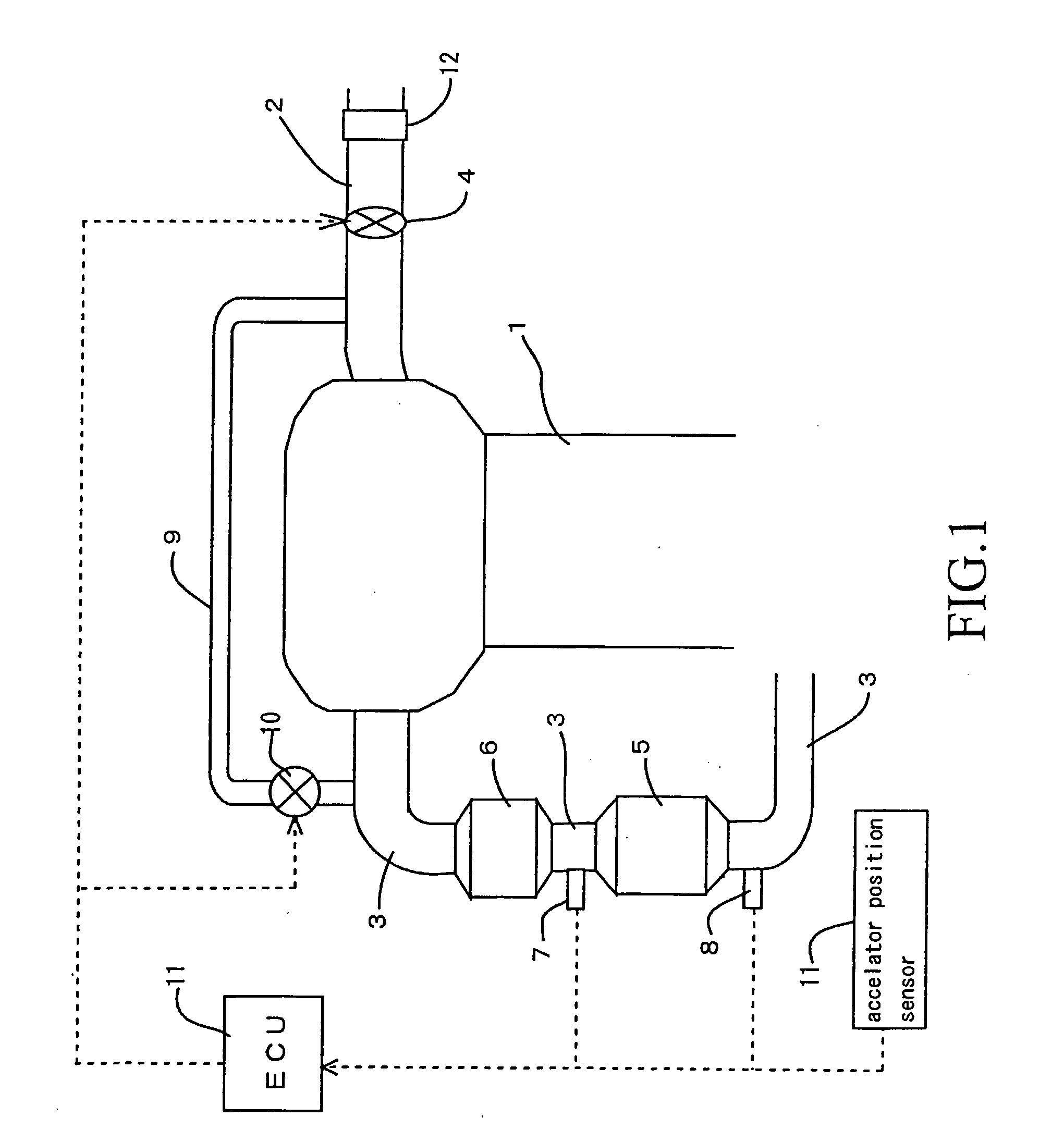
[0155] An example of the method of estimating the outflowing exhaust gas temperature at the end of the deceleration idling period by calculation is making a model of the heat budget of the exhaust system extending from the upstream exhaust gas temperature sensor 7 to the downstream exhaust gas temperature sensor 8 and estimating the outflowing exhaust gas temperature by calculation using that model.

[0156] The above-mentioned model may be divided into the first model for the heat budget of the exhaust system extending from the upstream exhaust gas temperature sensor 7 to the particulate filter 5, the second model for the heat budget in the particulate filter 5 and the thir...


PUM

PropertyMeasurementUnit
exhaust gas temperatureaaaaaaaaaa
temperatureaaaaaaaaaa
pressureaaaaaaaaaa

Abstract

An object of the invention is to realize a method of determining an abnormality in a particulate filter (5) capable of trapping and oxidizing particulate matter contained in exhaust gas in which even a minor abnormality in which small quantity of particulate matter can pass through the particulate filter (5) can be determined with a high degree of accuracy. To achieve this object, the abnormality determination method according to the invention, the transition of the inflowing exhaust gas temperature in and the outflowing exhaust gas temperature out of the particulate filter (5) during deceleration operating, and the degree of decrease in the outflowing exhaust gas temperature relative to the inflowing exhaust gas temperature is computed based on the transition. If the degree of decrease exceeds a threshold value, it is determined that the particulate filter (5) is abnormal.

Description

TECHNICAL FIELD [0001] The present invention relates to a technology for determining an abnormality in a particulate filter provided in an exhaust passage of an internal combustion engine. BACKGROUND ARTS [0002] In recent years, various technologies for determining an abnormality in a particulate filter in an internal combustion engine used in a vehicle etc. have been proposed. In a known technology for determining a filter abnormality, as disclosed in Japanese Patent Publication No. 3-38406, an abnormality in a filter is determined based on a comparison of the exhaust gas pressure in the upstream of the filter at a predetermined time after start of filter regeneration and a reference pressure that is determined by the operating state of the engine at that time. [0003] Japanese Patent Application Laid-Open No. 6-323127 discloses a technology of determining an abnormality in a filter by comparing the pressure difference between the upstream and the downstream of the filter just after...

Claims


Application Information

Patent Timeline
Patent Type & Authority Applications(United States)
IPC IPC(8): F01N11/00B01D46/42B01D53/94F01N3/035F01N3/24F01N13/02F02D9/02F02D21/08F02D41/12F02D41/22F02D45/00
CPCF01N3/035F01N11/002F01N11/005F01N2550/04F01N13/009F02D41/0055F02D41/12Y02T10/47F01N2900/0422Y02T10/40
Inventor SAWADA, HIROSHISHIBATA, DAISUKEFUKUOKA, KEISUKE
Owner TOYOTA JIDOSHA KK
Why Eureka
Try Eureka