Controlling The Flow Of A Multiphase Fluid From A Well

a multi-phase fluid and well technology, applied in the direction of fluid removal, survey, borehole/well accessories, etc., can solve the problems of flow stability, particular problems, and severe instabilities of the gas/liquid ratio of the fluid produced up the tubing

Inactive Publication Date: 2008-02-21
SHELL OIL CO
View PDF10 Cites 16 Cited by
  • Summary
  • Abstract
  • Description
  • Claims
  • Application Information

AI Technical Summary

Benefits of technology

[0025] In accordance with the invention there is also provided a well extending into a subsurface formation for producing a multiphase fluid to surface, which well is provided at a downstream position with a valve having a variable aperture, and with a control system for controlling the multiphase flow, which control system includes means for measuring a flow parameter of the multiphase fluid, which flow parameter is responsive to changes in a gas / liquid ratio of the multiphase fluid at an upstream position in the well, and a means for controlling the flow parameter towards a selected setpoint by manipulating the aperture of the valve, wherein the control system is so arranged that the control time between detection of a deviation from the setpoint and the manipulation of the aperture is shorter than the time needed for the multiphase fluid to travel 25% of the distance between the upstream and downstream positions.

Problems solved by technology

Upward multiphase fluid flow in a well can often lead to flow stability problems.
Particular problems are encountered in gas-lifted wells, in which gas is injected from surface via a casing / tubing annulus and an injection valve upstream in the well into the production tubing.
Also here, severe instabilities of the gas / liquid ratio of the fluid produced up the tubing can occur.
A special problem is observed in dual gas-lifted wells, wherein two tubings are arranged, usually with inlets for reservoir fluid at different depths.
A common problem there is that production through one of the tubings ceases, due to instabilities in the lift gas injection into the tubings.
Heading is generally undesirable, not only because of production loss, but also because downstream fluid handling equipment such as separators and compressors can be upset, damaging of the wellbore or flowline, and negative influences on other wells connected the same equipment.

Method used


Image

  • Controlling The Flow Of A Multiphase Fluid From A Well
  • Controlling The Flow Of A Multiphase Fluid From A Well
  • Controlling The Flow Of A Multiphase Fluid From A Well

Examples


Embodiment Construction

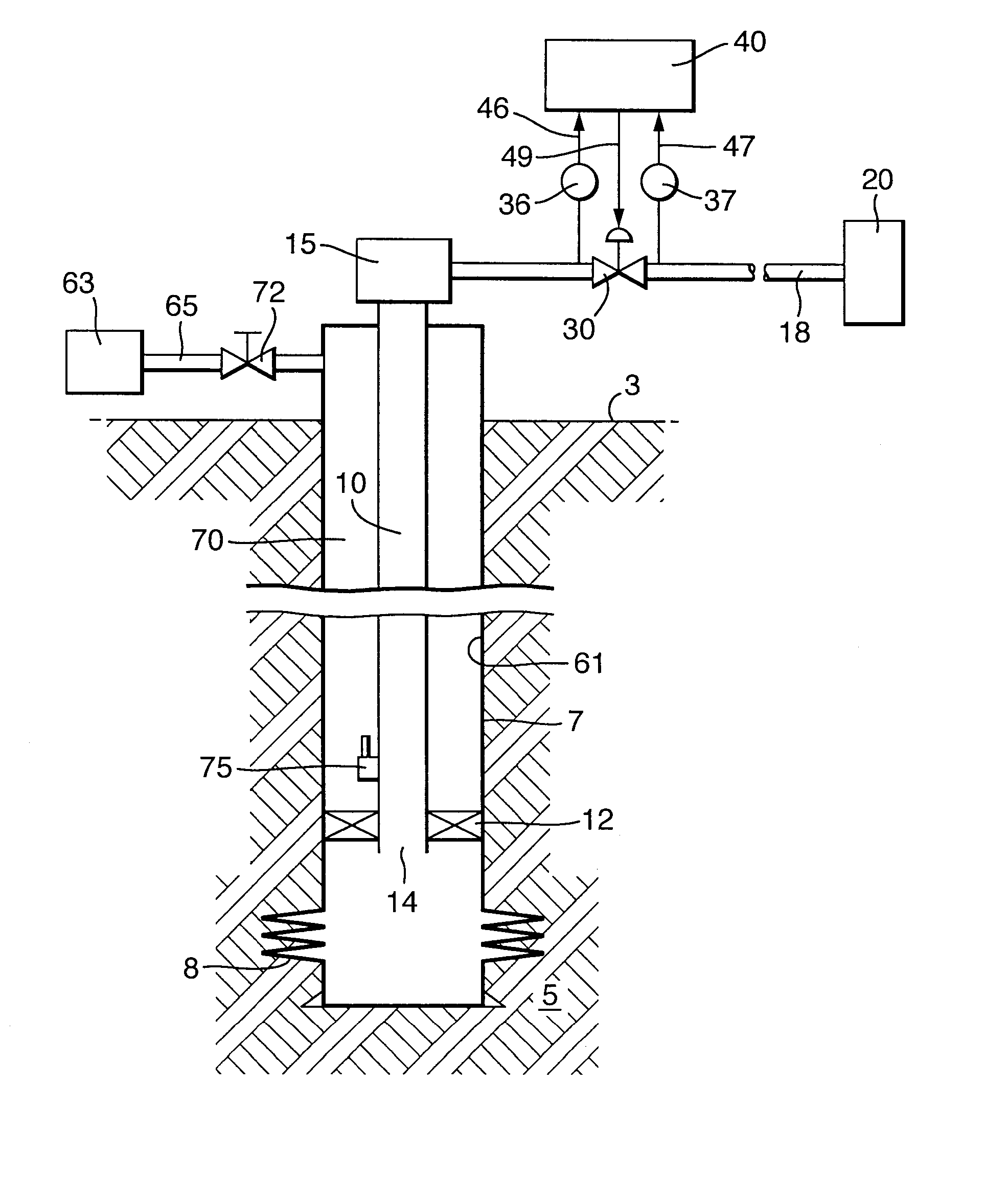
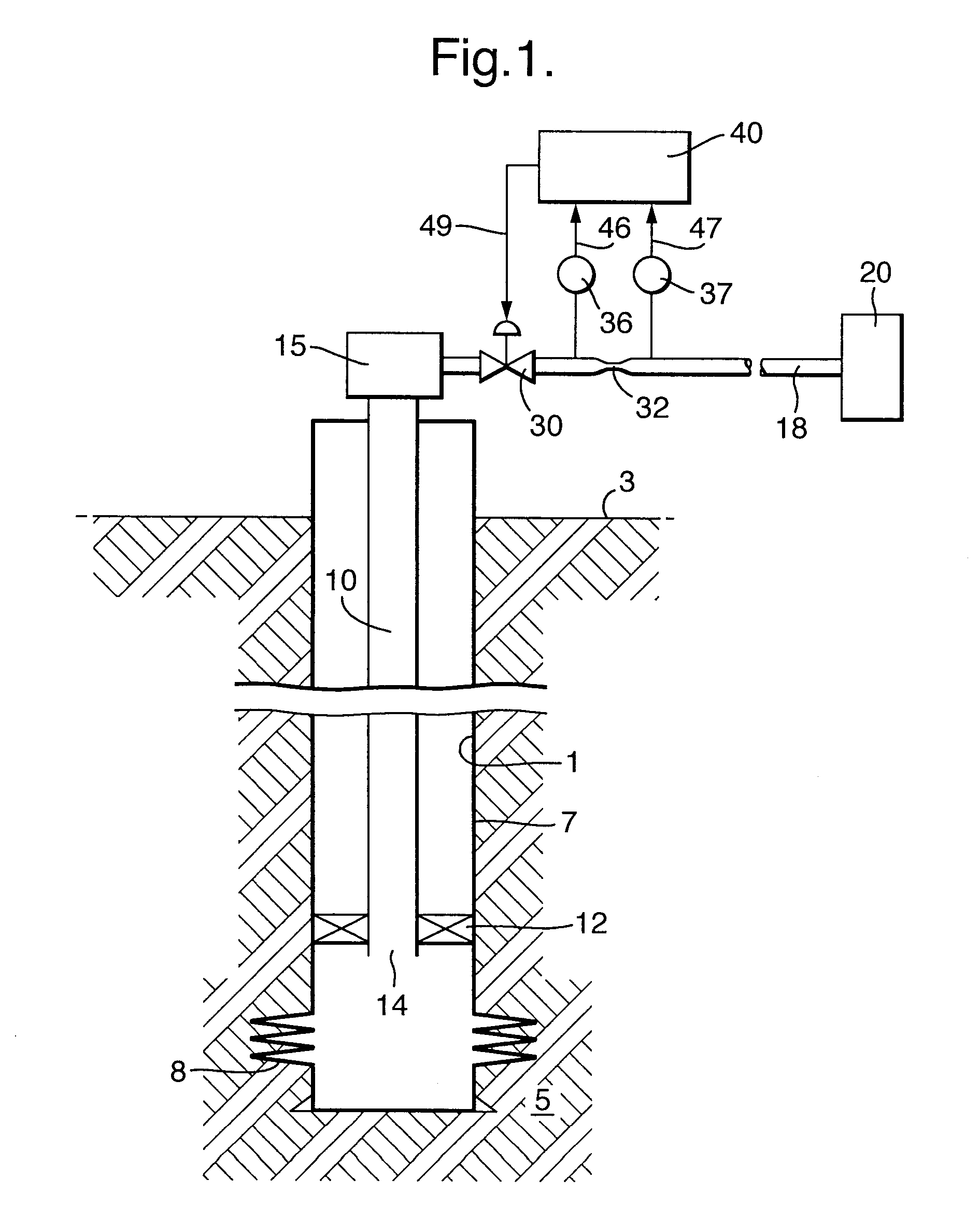
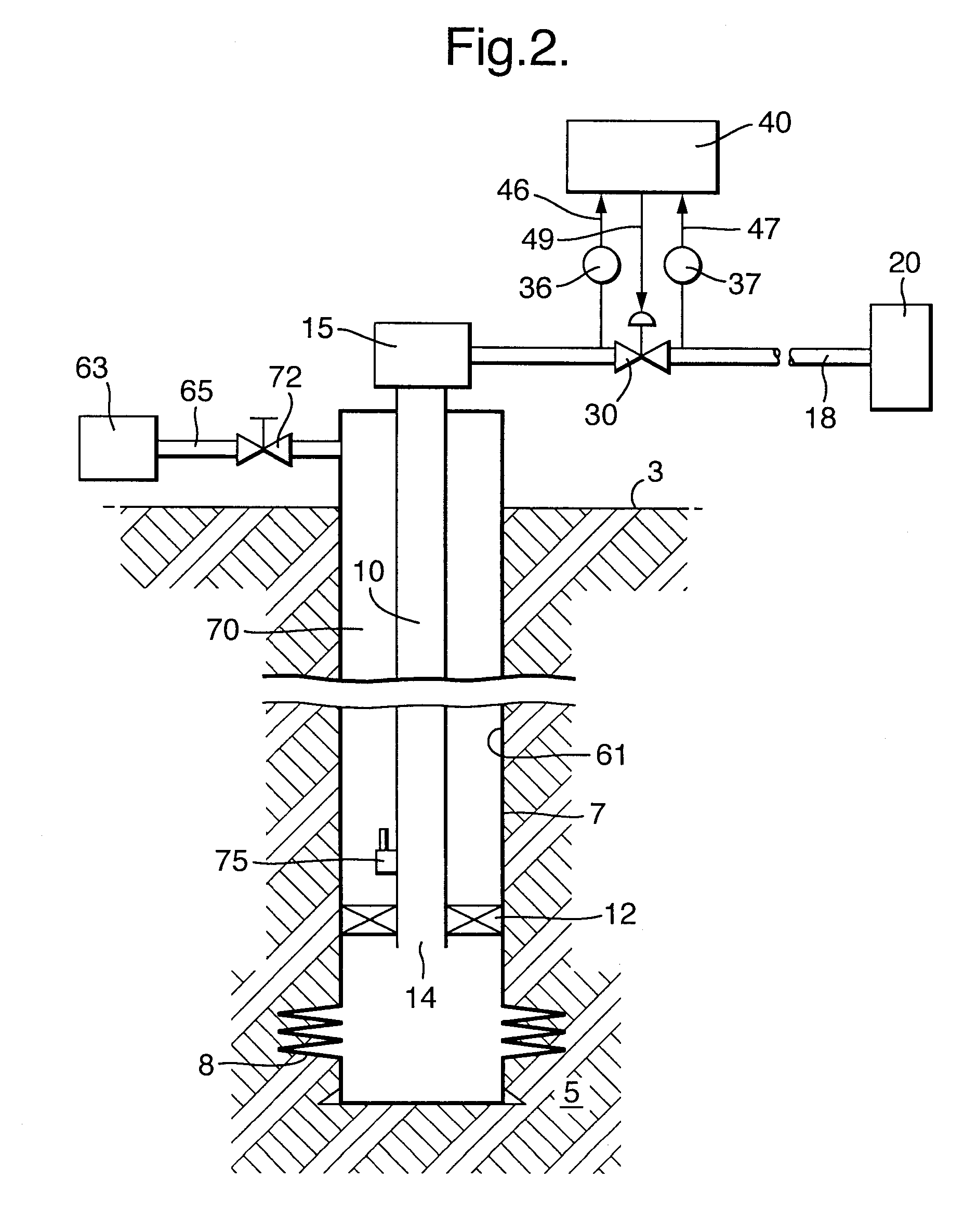
[0030] Reference is made to FIG. 1. The Figure shows a free-flowing well 1 extending from surface 3 into a subsurface formation 5. The well is provided with casing 7, and at the lower end of the well perforations 8 are arranged for receiving reservoir fluid into the well. Production tubing 10 is installed, separated by a packer 12 from the casing. The production tubing extends from its upstream end 14 to a wellhead 15 at surface, and from there through a flowline 18 to downstream processing equipment 20, e.g. including a gas / liquid separator. Along the flowline a control system is arranged, comprising a controllable variable valve 30, a flow restriction 32, pressure sensors 36 and 37 upstream and downstream of the flow restriction, and a controller 40 receiving input via lines 46,47 from the pressure sensors 36,37, and having an output via line 49 for a control signal to the controllable valve 30. In a particular embodiment (not shown, but see FIG. 2), the variable valve 30 is place...


PUM


Abstract

A method for controlling the flow of a multiphase fluid from a well extending into a subsurface formation, which well is provided at a downstream position with a valve having a variable aperture, which method comprises allowing the multiphase fluid to flow at a selected aperture of the valve; selecting a flow parameter of the multiphase fluid, which flow parameter is responsive to changes in a gas/liquid ratio of the multiphase fluid at an upstream position in the well, and a setpoint for the flow parameter; and monitoring the flow parameter; controlling the flow parameter towards its setpoint by manipulating the aperture of the valve; wherein the control time between detection of a deviation from the setpoint and the manipulation of the aperture is shorter than the time needed for the multiphase fluid to travel 25% of the distance between the upstream and downstream positions. Further a well extending into a subsurface formation for producing a multiphase fluid to surface, which well is provided at a downstream position with a valve having a variable aperture, and with a control system for controlling the multiphase flow.

Description

FIELD OF THE INVENTION [0001] The present invention relates to a method for controlling the flow of a multiphase fluid from a well extending into a subsurface formation. BACKGROUND OF THE INVENTION [0002] Multiphase flow of liquid such as oil and / or water, and gas, is almost always involved in the production of hydrocarbons from subsurface formations. Upward multiphase fluid flow in a well can often lead to flow stability problems. [0003] Production instabilities can be encountered for example in the form of large fluctuations of the oil production rate, e.g. more than 25% of the average production rate, or in situations where big slugs of oil are alternated by gas surges. Particular problems are encountered in gas-lifted wells, in which gas is injected from surface via a casing / tubing annulus and an injection valve upstream in the well into the production tubing. Also here, severe instabilities of the gas / liquid ratio of the fluid produced up the tubing can occur. A special problem...

Claims


Application Information

Patent Timeline
Patent Type & Authority Applications(United States)
IPC IPC(8): E21B43/12E21B43/00
CPCE21B43/121E21B43/12
Inventor EKEN, ADRIAAN NICOLAAS
Owner SHELL OIL CO
Why Eureka
Try Eureka