
Shelf light bracket connector system

a technology for connectors and shelves, applied in the field of shelves, can solve the problems of difficulty in concealing wiring, affecting the appearance of shelves, and the number of shelves, and achieve the effect of reducing the possibility

Inactive Publication Date: 2008-02-21
R3 CONNECTOR SYST
View PDF5 Cites 89 Cited by
  • Summary
  • Abstract
  • Description
  • Claims
  • Application Information

AI Technical Summary

Benefits of technology

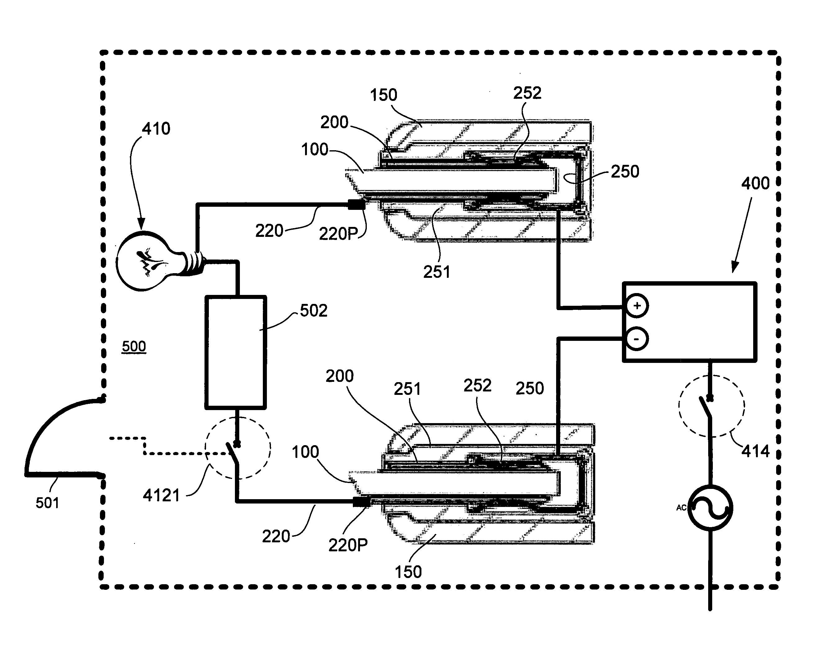
[0012]One embodiment incorporates an insulator which fits into the rear of the vertical channel support bracket or rail element of the shelving structure and encloses therein a shaped, electrically conductive contact strip. This insulator can be molded in a manner that permits the contact strip to snap into place or, alternatively foldable so that the contact strip to be placed in position and the insulator folded about the strip to enclose the same and thus facilitate production of the arrangement.
[0023]The contact clips on the ends of the shelf brackets are exposed when the shelf is removed, but they are not “live” until in contact with the contact strips within the vertical support brackets. In addition, their placement and the incorporation of the wire into the shelf itself further attenuates the possibility of anyone accidentally touching any “live” surface.

Problems solved by technology

This of course is, in the case of even a moderate number of shelves, both laborious and time consuming.
This type of arrangement, which is often referred to as a “cantilever rack”, is readily assembled / dissembled, however again suffers from the drawback that when shelf lighting is required, such as in the case where goods and products are displayed in a supermarket for example, the lighting elements and wiring must be separately and often painstakingly connected to the shelf.
In addition, the wiring is, in some instances, difficult to conceal.
Further, particularly where the general public is concerned, it is undesirable for an individual (i.e. a layperson) who is not qualified to handle electrical wiring, to install the shelf and to safely make the separate electrical connections which are necessary for the desired lighting, even in the case of low voltage lighting such as that which uses LED as a light source.

Method used


Image

  • Shelf light bracket connector system
  • Shelf light bracket connector system
  • Shelf light bracket connector system

Examples


Embodiment Construction

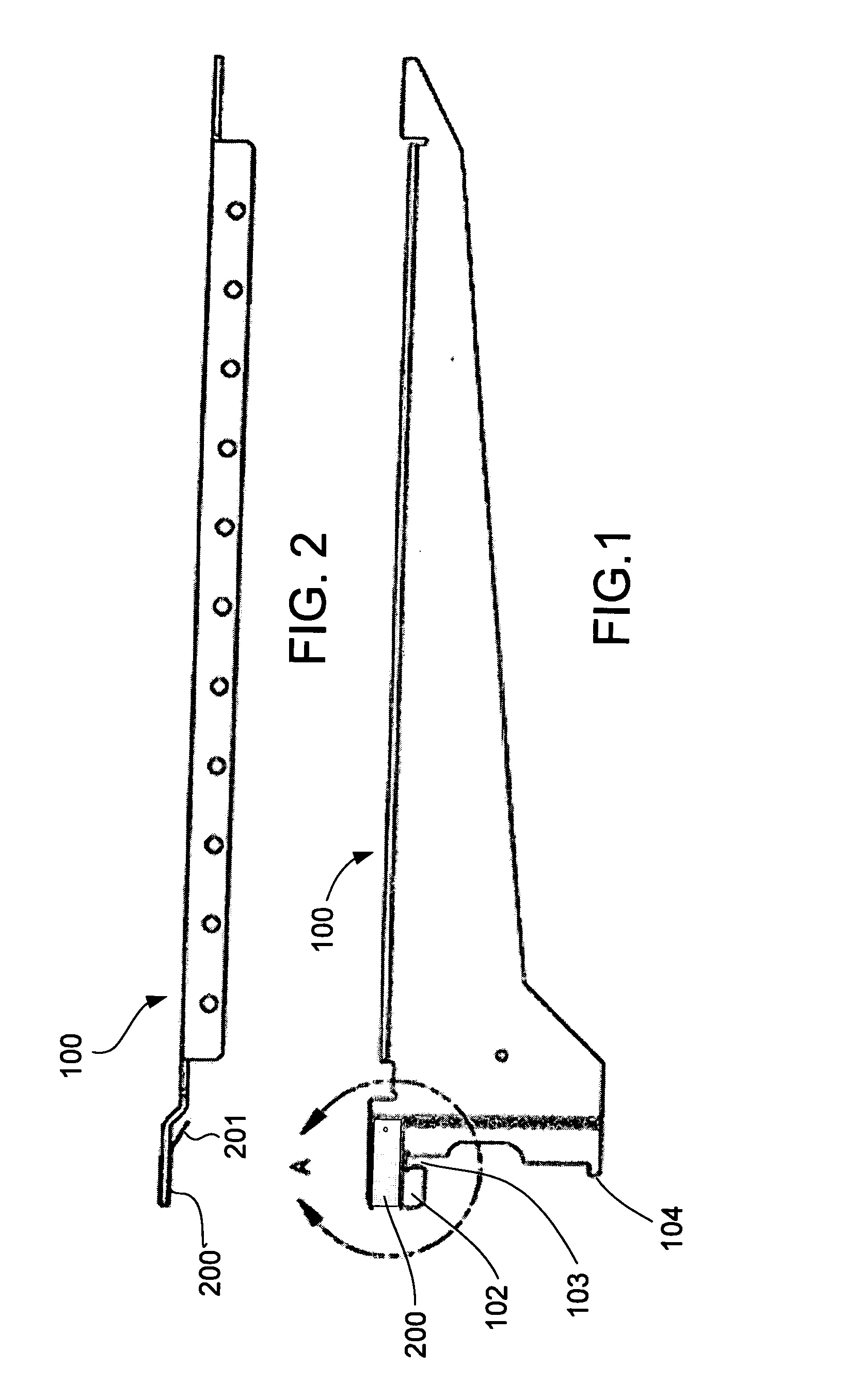
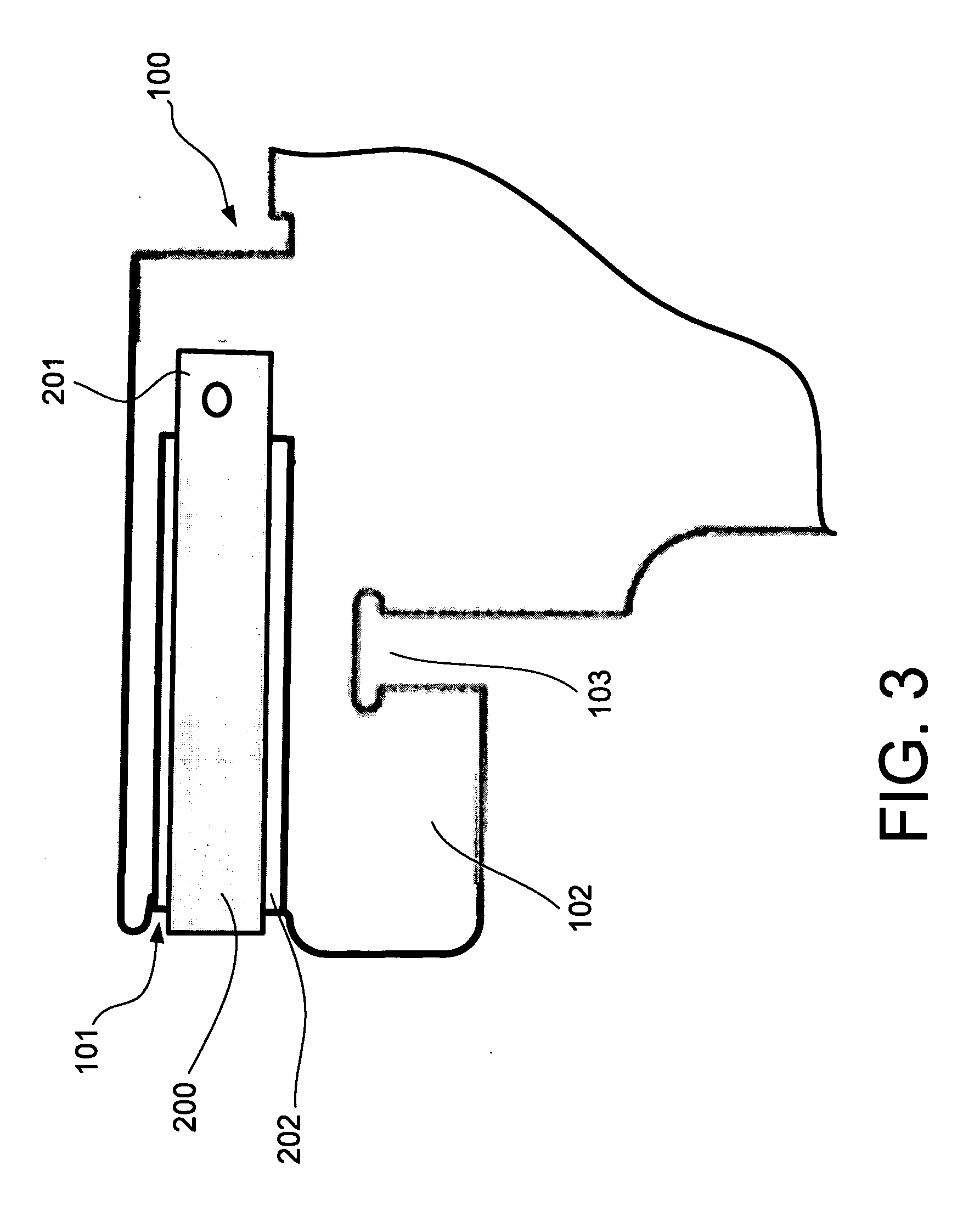
[0047]A shelf bracket 100 is illustrated in FIGS. 1 and 2, which is provided with a male electrical connection feature in accordance with an embodiment of the present invention. In this particular embodiment, this electrical connection feature takes the form of a clip 200, which is fitted onto a rear edge of the shelf bracket. To insulate the clip 200 from the electrically conductive material of the shelf bracket 100, a layer of electrically insulative tape 202 (see FIG. 3) is provided between the clip 200 and the shelf bracket 100. To facilitate production / assembly, this tape 202 can be adhesive either one or both sides and is arranged in the manner best appreciated from FIG. 6.

[0048]It should be noted that the embodiments of the invention are not limited to the use of clips of the nature illustrated and that other forms of electrical contact can be used without departing from the scope and spirit of the invention.

[0049]To appropriately locate the clip 200 and the tape 202 on the r...


PUM


Abstract

A shelf arrangement has an electrical connector which is disposed with one of a plurality of mechanical connection elements of a shelf bracket wherein the connection elements are configured to be received in openings formed in a vertical support bracket; and a contact strip which is disposed with the vertical support bracket and which has electrical connection features that are engageable with the electrical connector to establish an electrical connection therebetween when the mechanical connection elements are inserted into the openings.

Description

BACKGROUND OF THE INVENTION[0001]1. Field of the Invention[0002]The present invention relates generally to shelves which are equipped with lighting fixtures for the purposes of displaying articles, books and the like. More specifically, the present invention relates to a connector system which enables electrical connections to be simply and easily established at the same time as the shelves are set into place.[0003]2. Brief Description of the Related Art[0004]Today, shelves incorporating discrete lighting fixtures either underneath (to illuminate a lower shelf) or on the side of the compartment, are in wide use. However, with such shelf arrangements, electrical wiring must be connected between the lighting fixtures which are incorporated into the shelves and a power outlet / socket or the like. In the event of shelf removal and / or shelf location change / rearrangement, the electrical wiring must be separately disconnected and reconnected. This of course is, in the case of even a moderat...

Claims


Application Information

Patent Timeline
IPC IPC(8): F25D27/00
CPCA47B57/42A47B97/00A47B2220/0077H01R25/16F21Y2101/02F25D25/02F25D27/00F21V33/0012F21Y2115/10
Inventor BERNARDINI, ALLEN J.GRISWOLD, ERIC A.
Owner R3 CONNECTOR SYST
Learn More