
Wireless communication terminal and wireless communication method

Inactive Publication Date: 2008-02-21
NTT DOCOMO INC
View PDF11 Cites 17 Cited by
  • Summary
  • Abstract
  • Description
  • Claims
  • Application Information

AI Technical Summary

Benefits of technology

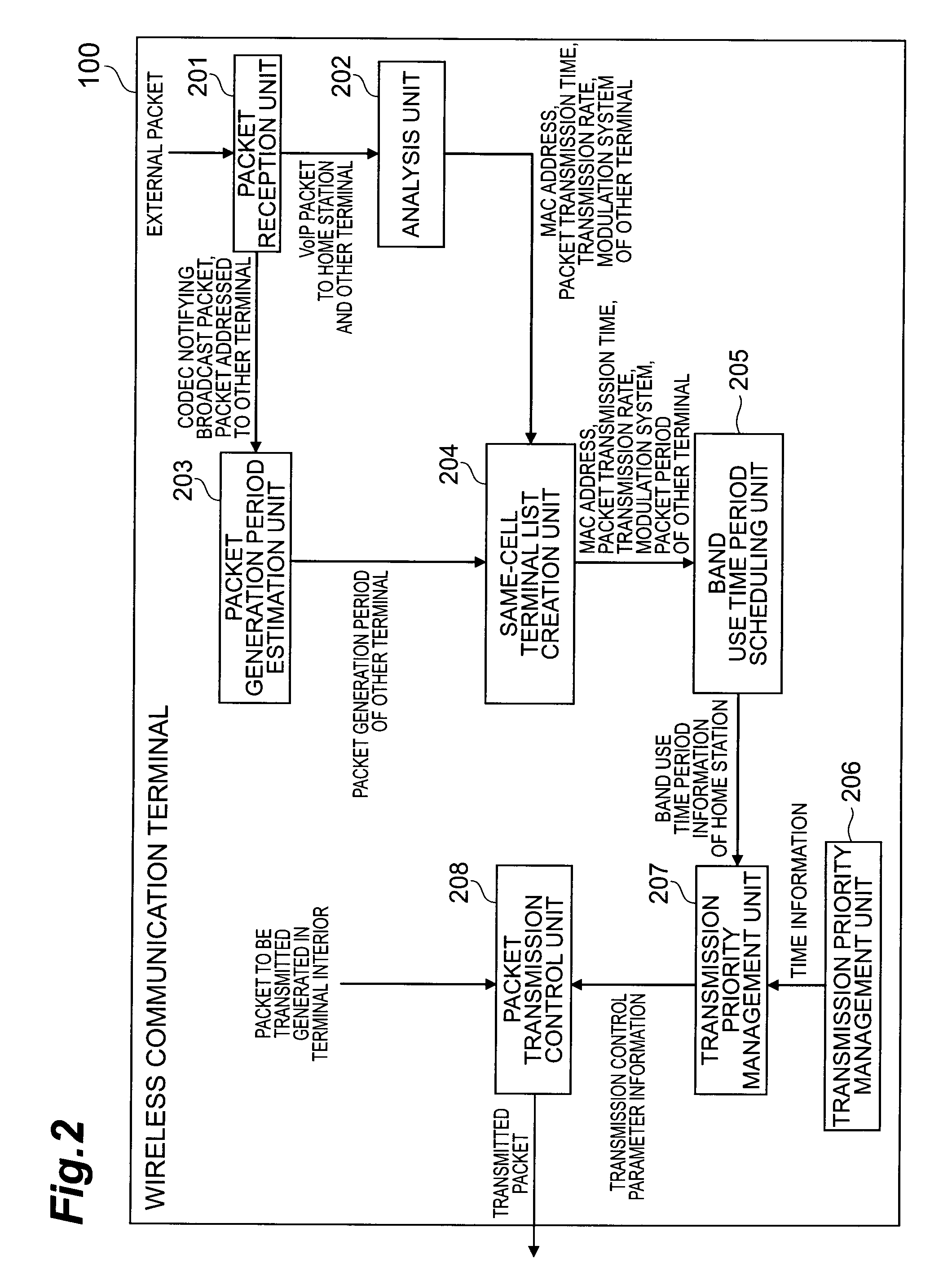
[0012]The packet generation period estimating module is preferably configured to estimate the packet generation period of the other terminal by (1) receiving packets from the wireless base station for a predetermined amount of time, (2) decoding destination MAC addresses described in the received packets, and (3) observing the packet generation period of packets having an identical destination MAC address. Thus, even when VoIP terminals using unknown voice codecs coexist, the packet generation period of the VoIP terminals can be estimated without generating a new overhead that compresses the wireless band.
[0013]Further, the second information obtaining module is preferably configured to obtain transmission rate information described in the packet, and the packet generation period estimating module is preferably configured to hold in advance a table describing a relationship between (1) codec types and periods and (2) packet lengths when packets are generated using the codec, calculate a packet length on the basis of the required transmission time information and the transmission rate information obtained by the second information obtaining module, determine a codec period of the other terminal by referring to the table using the calculated packet length as a key, and estimate the packet generation period from the codec period. Thus, as long as one downward voice packet can be received from the wireless base station, the voice codec used by the destination terminal of the packet can be recognized, and as a result, the packet generation period of the destination terminal can be recognized without generating a new overhead that compresses the wireless band.
[0015]Further, a plurality of wireless communication terminals having an identical packet length are preferably grouped together, and packet generation period estimating module of only one predetermined wireless communication terminal within each group is preferably configured to broadcast the packet describing the codec period used by the wireless communication terminal or the packet generation period of the wireless communication terminal. Thus, even when terminals using unknown codecs coexist, the packet generation periods of the terminals can be recognized without observing a plurality of data packets over a fixed time period and so as to suppress the generation of new overheads that compress the wireless band to a minimum.
[0016]Further, the second scheduling module is preferably configured to group together terminals having an identical packet generation period from among the packet generation period of the other terminal estimated by the packet generation period estimating module and the packet generation period of the wireless communication terminal, set a temporary band use time period in order of MAC address for each terminal in each group, by setting the temporary band use time period of each terminal as to be longer than or equal to the time required to perform the packet transmission / reception procedure calculated by the time calculating module of each terminal, and set all of the temporary band use time periods in all of the groups as final band use time periods for all of the terminals in order from the temporary band use time period having the earliest start time, and when an attempt is made to set a temporary band use time period at a time in which another band use time period has already been set, set the temporary band use time period as a final band use time period at the end of the other band use time period. Thus, even when terminals having different packet generation periods coexist, transmission timing allocation can be performed so as to suppress fluctuation in the packet transmission interval of each terminal to a minimum.
[0024]According to the present invention, in a case where an application that is required to transmit packets periodically, such as VoIP, is used on a wireless LAN, an appropriate transmission timing can be determined in a plurality of wireless communication terminals in an autonomous distributed manner even when the wireless communication terminals have different terminal properties (transmission rates, packet generation periods, and supportable modulation systems), and as a result, an improvement in communication quality can be achieved.

Problems solved by technology

When a plurality of terminals perform packet transmission simultaneously, a packet collision occurs such that none of the terminals can receive packets correctly, and as a result, the communication quality deteriorates.
A particularly striking deterioration in the communication quality occurs in a real time application such as VoIP.
However, conventional EDCA is merely a technique for attaching an order of relative transmission precedence to a plurality of packets having different set priorities, and not for ensuring quality among and attaching priority to a plurality of terminals that transmit packets having the same set priority.
When a packet collision occurs, retransmission is delayed even if successful, and when retransmission fails, packet loss occurs.
Furthermore, when a plurality of terminals perform back-off to obtain packet transmission rights, another terminal from which the transmission rights are obtained faces an increased transmission wait time, or in other words a delay, to re-obtain transmission rights.
The probability of a packet collision increases as the number of terminals rises, and the probability of delays and packet loss increases accordingly.
A particularly great deterioration in quality may occur when delays and packet loss occur in a real time application such as VoIP (Voice over Internet Protocol).
However, the technique described in Japanese Unexamined Patent Application Publication 2005-252627 is merely a method of having a wireless base station schedule the transmission timing of a wireless communication terminal, and the wireless communication terminal itself is not capable of scheduling the transmission timing in an autonomous distributed manner.
Furthermore, although the technique described in Japanese Unexamined Patent Application Publication 2005-252627 is a protocol according to which scheduling can only be performed when the wireless base station recognizes the packet generation period of all of the wireless communication terminals, a method of ensuring that the wireless base station recognizes the packet generation period of all of the wireless communication terminals is not realized.

Method used


Image

  • Wireless communication terminal and wireless communication method
  • Wireless communication terminal and wireless communication method
  • Wireless communication terminal and wireless communication method

Examples


first embodiment

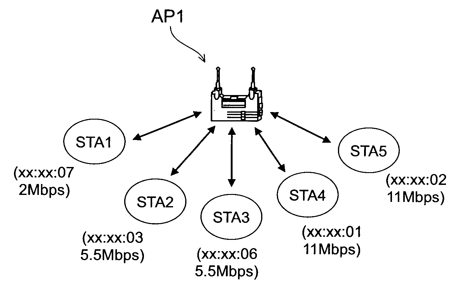
[0069]First, as the first embodiment, a case in which wireless communication terminals having different transmission rates coexist and all of the terminals use the same voice codec will be described.

[0070]As shown in FIG. 3, a wireless LAN network is constituted by an AP1, serving as a single wireless base station, and a plurality of wireless communication terminals. Here, the plurality of wireless communication terminals are differentiated by the reference symbols STA1 to STA5. As shown in parentheses in FIG. 3, the MAC addresses and transmission rates of the respective wireless communication terminals are as follows: in the STA1, the MAC address is xx:xx:07 and the transmission rate is 2 Mbps; in the STA2, the MAC address is xx:xx:03 and the transmission rate is 5.5 Mbps; in the STA3, the MAC address is xx:xx:06 and the transmission rate is 5.5 Mbps; in the STA4, the MAC address is xx:xx:01 and the transmission rate is 11 Mbps; and in the STA5, the MAC address is xx:xx:02 and the ...

second embodiment

[0083]Next, as the second embodiment, a case in which wireless communication terminals having different voice codecs coexist and all of the terminals use the same transmission rate will be described.

[0084]As shown in FIG. 12, a wireless LAN network is constituted by an AP2, serving as a single wireless base station, and a plurality of wireless communication terminals. Here, the plurality of wireless communication terminals are differentiated by the reference symbols STA11 to STA15. As shown in parentheses in FIG. 12, the MAC addresses and voice codecs of the respective wireless communication terminals are as follows: in the STA11, the MAC address is xx:xx:11 and the voice codec is G.711 with a period of 20 ms; in the STA12, the MAC address is xx:xx:12 and the voice codec is G.711 with a period of 20 ms; in the STA13, the MAC address is xx:xx:13 and the voice codec is G.711 with a period of 20 ms; in the STA14, the MAC address is xx:xx:14 and the voice codec is G.729 with a period of...

third embodiment

[0110]Next, as the third embodiment, a case in which wireless communication terminals having different transmission rates and different voice codecs coexist will be described.

[0111]As shown in FIG. 18, a wireless LAN network is constituted by an AP3, serving as a single wireless base station, and a plurality of wireless communication terminals. Here, the plurality of wireless communication terminals are differentiated by the reference symbols STA21 to STA25. As shown in parentheses in FIG. 18, the MAC addresses, transmission rates, and voice codecs of the respective wireless communication terminals are as follows: in the STA21, the MAC address is xx:xx:26, the voice codec is G.711 with a period of 20 ms, and the transmission rate is 5.5 Mbps; in the STA22, the MAC address is xx:xx:27, the voice codec is G.729 with a period of 30 ms, and the transmission rate is 5.5 Mbps; in the STA23, the MAC address is xx:xx:23, the voice codec is G.711 with a period of 20 ms, and the transmission ...


PUM


Abstract

A wireless communication terminal comprises: a packet receiving unit for receiving a packet from a wireless base station; module for obtaining a transmission rate and a required transmission time from the received packet; module for calculating a time required to perform a packet transmission / reception procedure on the basis of the required transmission time; an analysis unit that functions as module for recognizing the existence of other terminal by decoding a destination MAC address described in the packet when the obtained transmission rate is equal to or lower than a transmission rate used by the wireless communication terminal; and a same-cell terminal list creation unit and band use time period scheduling unit for setting a band use time period that is equal to or greater than the time required to perform the packet transmission / reception procedure, for a time period, within a predetermined period corresponding to a packet generation period, regarding the other terminal and the wireless communication terminal, in order from the terminal having the lowest transmission rate.

Description

BACKGROUND OF THE INVENTION[0001]1. Field of the Invention[0002]A present invention relates to a wireless LAN communication system, and more particularly to communication priority control in a CSMA / CA (Carrier Sense Multiple Access with Collision Avoidance) system.[0003]2. Related Background Art[0004]In a CSMA / CA system, a terminal performs virtual carrier sensing, to be described below, for a random time period prior to communication to check whether another terminal is communicating with a base station, and when another terminal is communicating, waits for the communication to end and then performs actual packet transmission. At this time, all terminals have equal transmission rights. In virtual carrier sensing, a random number is generated within a prescribed CW (Contention Window) range after a channel has been idle for an IFS (Inter Frame Space) time period, and a random time period is determined on the basis of the value of the random number. Back-off control, to be described ...

Claims


Application Information

Patent Timeline
IPC IPC(8): H04Q7/24H04B7/212H04L12/413H04W72/12H04W74/08H04W84/12H04W88/10
CPCH04L12/2602H04L25/0262H04L25/05H04W88/10H04W72/121H04W72/1268H04L43/00
Inventor IGARASHI, KEIYAMADA, AKIRA
Owner NTT DOCOMO INC
Learn More