Turbomachine with reduced leakage penalties in pressure change and efficiency

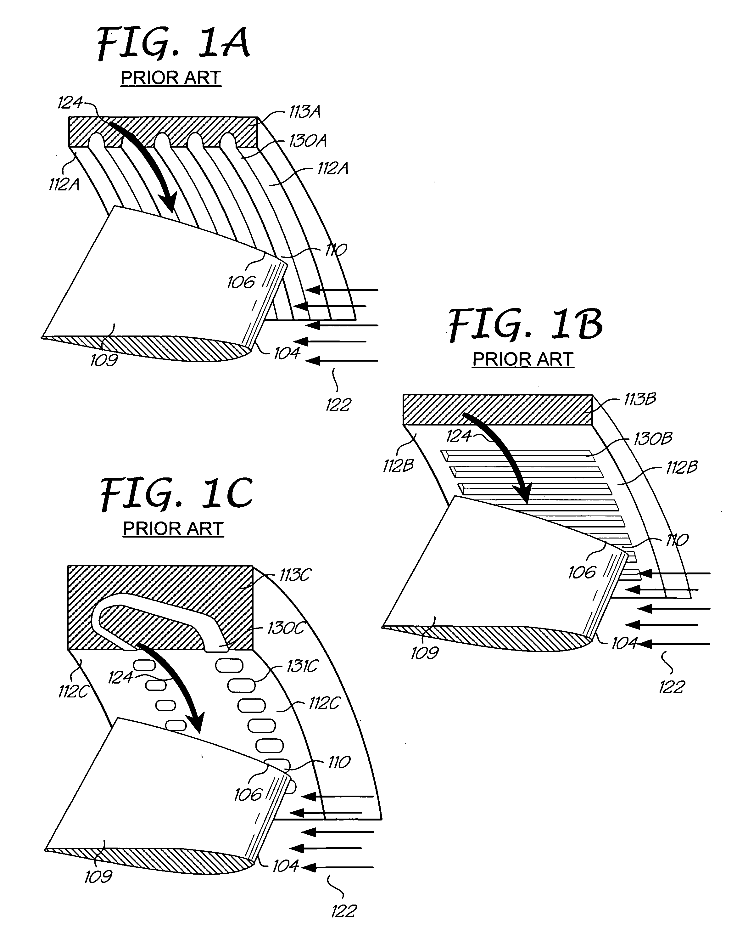
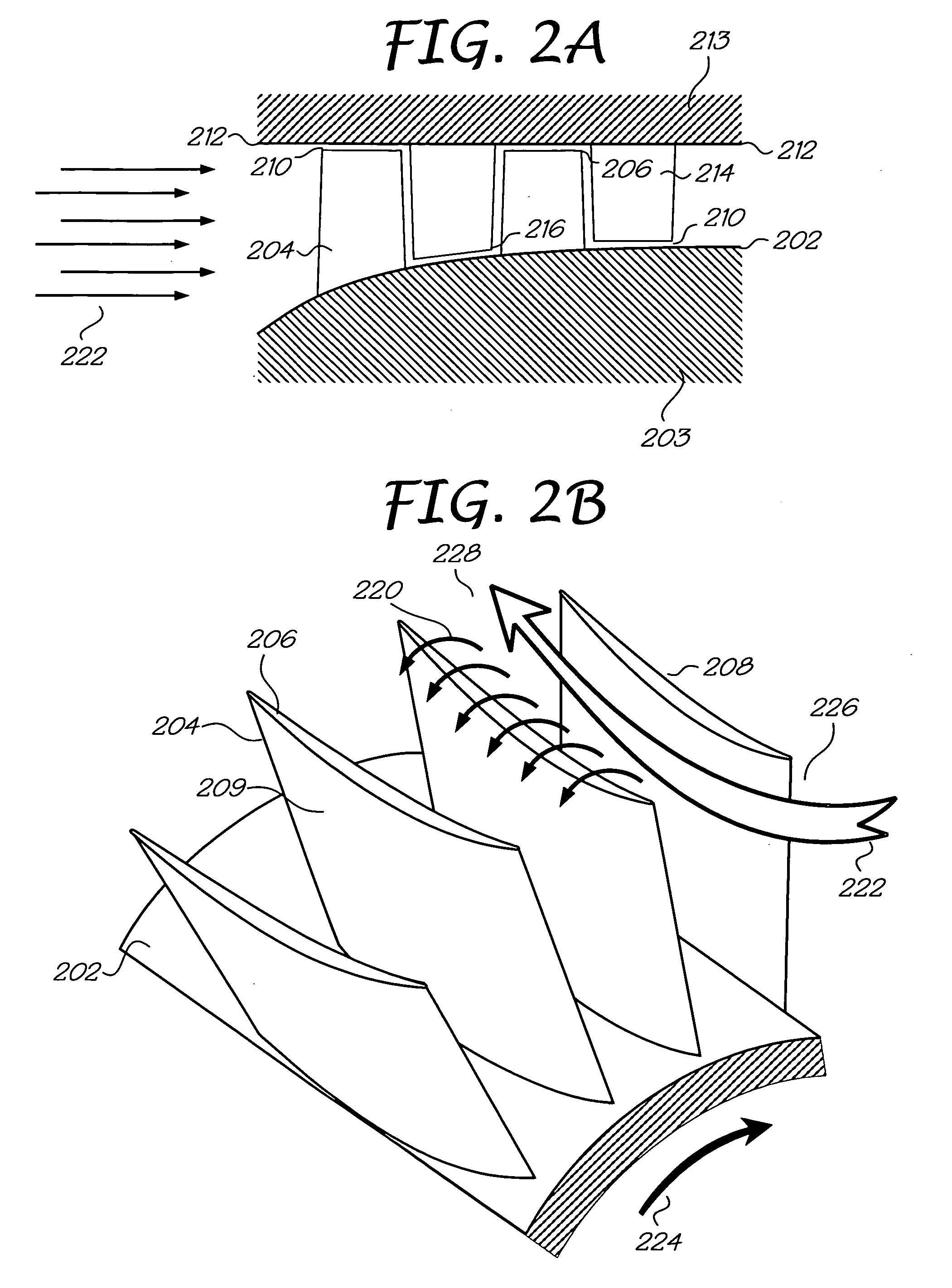
a turbine and valve technology, applied in the field of turbines, can solve the problems of reducing efficiency, reducing the effective flow area, and reducing the clearance across substantially all blade tips, so as to reduce the adverse effects of tip leakage and reduce the flow recirculation within the groov

Inactive Publication Date: 2008-02-21
KHALID SYED ARIF
View PDF44 Cites 92 Cited by
  • Summary
  • Abstract
  • Description
  • Claims
  • Application Information

AI Technical Summary

Benefits of technology

[0016]The present invention is directed to a casing treatment for reducing the adverse effects of tip leakage over a blade in a turbomachine. A turbomachine is provided having at least one row of blades oriented at a predetermined stagger. Casing grooves are provided proximate to at least a portion of the tip of the blades. The grooves are orientated substantially normal to the stagger of the blades. The normal of the blade is determined from a chord of the blade. The chord may be taken across a pair of corresponding points, one toward the upstream end and the other toward the downstream end of the blade, hence across the extent of the cross-sectional shape of the blade. Alternatively, a blade chord may be determined over only a portion of the blade, for instance from a ...

Problems solved by technology

Viewed in the relative frame of the blade passage, it is widely known that the interaction between the tip leakage and main passage flow results in loss (reduced efficiency) and reduced effective flow area (reduced pressure rise for compressor or pump) at the exit of the passage.
Centrifugal forces cause the rotor and blades to elongate, resulting in the blade tips being displaced radially outward, thereby reducing the clearance across substantially all of the blade tip.
Fluid dynamic forces on the airfoil, on the other hand, cause the blades to deform axially and twist, thereby reducing the clearance of the blade tips away from the rotational a...

Method used


Image

  • Turbomachine with reduced leakage penalties in pressure change and efficiency
  • Turbomachine with reduced leakage penalties in pressure change and efficiency
  • Turbomachine with reduced leakage penalties in pressure change and efficiency

Examples


Embodiment Construction

Element Reference Number Designations

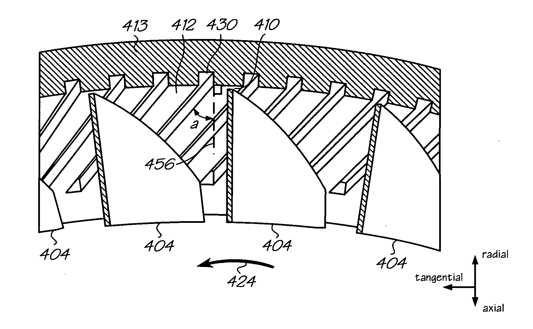
[0031]02: Hub surface[0032]03: Hub body[0033]04: Blade-rotating hub-mounted blade[0034]06: Tip of rotating blade[0035]08: Blade surface facing rotation direction[0036]09: Blade surface facing opposite rotation direction[0037]10: Gap (clearance) between tip of rotating hub-mounted blade[0038]12: Casing wall[0039]13: Casing body[0040]14: Vane (blade)—stationary casing mounted[0041]16: Tip of stationary vane[0042]18: Forward facing surface of stationary vane[0043]19: Aft facing surface of stationary vane[0044]20: Leakage flow over blade tip from high pressure side (pressure surface) to low pressure side (suction[0045]22: Direction of incoming flow[0046]24: Rotation direction[0047]26: Upstream limit of blade[0048]28: Downstream limit of blade[0049]30: Groove in stationary casing wall[0050]31: Groove start[0051]32: Groove peak[0052]33: Groove end[0053]40: Groove in rotating hub surface[0054]50: Normal to blade[0055]52: Chord line of airfoil[0056]54: C...


PUM


Abstract

A turbomachine is provided having at least one row of blades oriented at a predetermined stagger. Casing grooves are provided proximate to at least a portion of the tip of the blades. The grooves are oriented substantially normal to the stagger of the blades. The normal of the blade is determined from a chord of the blade. The chord may be taken across a pair of corresponding points one the upstream and downstream end of the blade, hence across the extent of the cross-sectional shape of the blade. Alternatively, a blade chord may be determined over only a portion of the blade, for instance, from a point along the centerline of the upstream end of the blade to a second point on the centerline midway down the blade from the upstream end. Optimally, the grooves are positioned adjacent to the upstream half of the blades, but may continue across the axial extent of the blades. The spacing between grooves can be optimized for blade stagger in order to find an optimal number of grooves that concurrently cross the blade. Additionally, obtaining an optimal groove depth for a particular turbomachine requires knowing only the tip clearance gap as groove depth is directly related to the tip clearance. Furthermore, since the groove may be substantially smaller than prior art casing treatments, fluid recirculation is reduced. The blade-normal groove may take a variety of cross-sectional shapes. Optimally, the aft surface of the groove will have less than a 45° incline to the radial at that point.

Description

BACKGROUND OF THE INVENTION[0001]1. Field of the Invention[0002]The present invention relates generally to turbomachinery. More particularly, the present invention relates to casing treatments for increasing the efficiency of fluid flow in a turbomachine.[0003]2. Description of Related Art[0004]In general, turbomachines utilize rows of blades on a hub (axle or wheel) that spin with respect to a stationary casing that encloses the hub and blades. Interleaved between the rows of rotating blades are rows of stationary vanes (or blades) disposed on the casing wall. As used herein internally, the terms blade, vane and airfoil will be used synonymously, although it is generally understood in the art that a blade is attached to the rotating hub or axle, while a vane is affixed to the stationary housing. The airfoil configuration of the blades is oriented on the hub at a precise angle, or stagger, with respect to the axis of rotation of the machine; similarly, the vanes are also oriented on...

Claims


Application Information

Patent Timeline
IPC IPC(8): F01D1/02
CPCF04D29/164F04D29/685F04D29/321F04D29/526
Inventor KHALID, SYED ARIF
Owner KHALID SYED ARIF
Why Eureka
Try Eureka