Air passage device

a filter mat and air passage technology, applied in the field of air passage devices, can solve the problems of scarce play and laborious installation of such filter mats, and achieve the effect of quick exchange of filter mats and no large structural expenditur

Inactive Publication Date: 2008-02-21
PFANNENBERG GMBH
View PDF7 Cites 41 Cited by
  • Summary
  • Abstract
  • Description
  • Claims
  • Application Information

AI Technical Summary

Benefits of technology

[0009] It is an object of the present invention to construct an air passage device according to the type described in the introduction so that it is possib...

Problems solved by technology

However, the installation of such filter fans is frequently laborious, because when screw connections are u...

Method used


Image

  • Air passage device
  • Air passage device
  • Air passage device

Examples


first embodiment

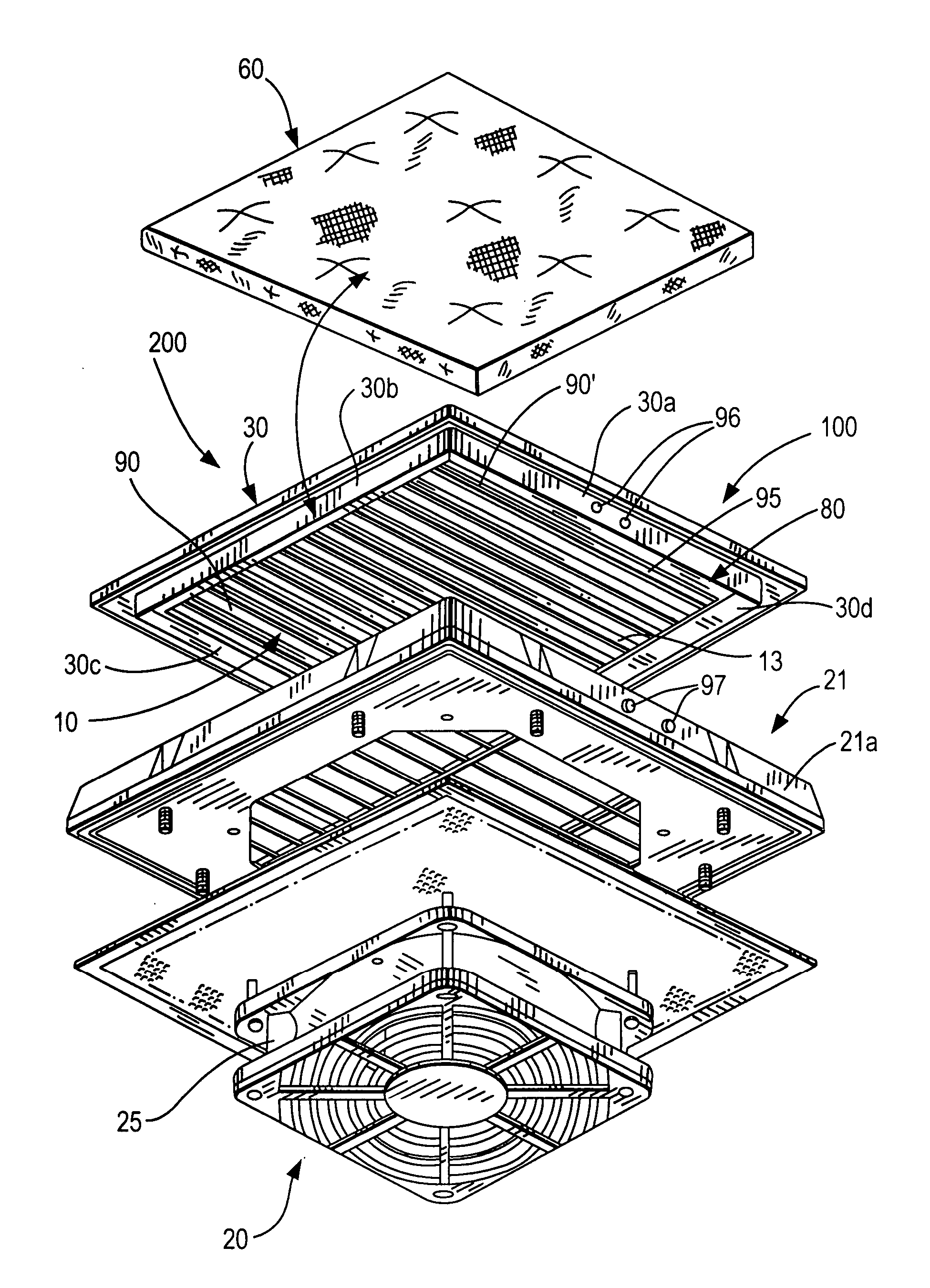
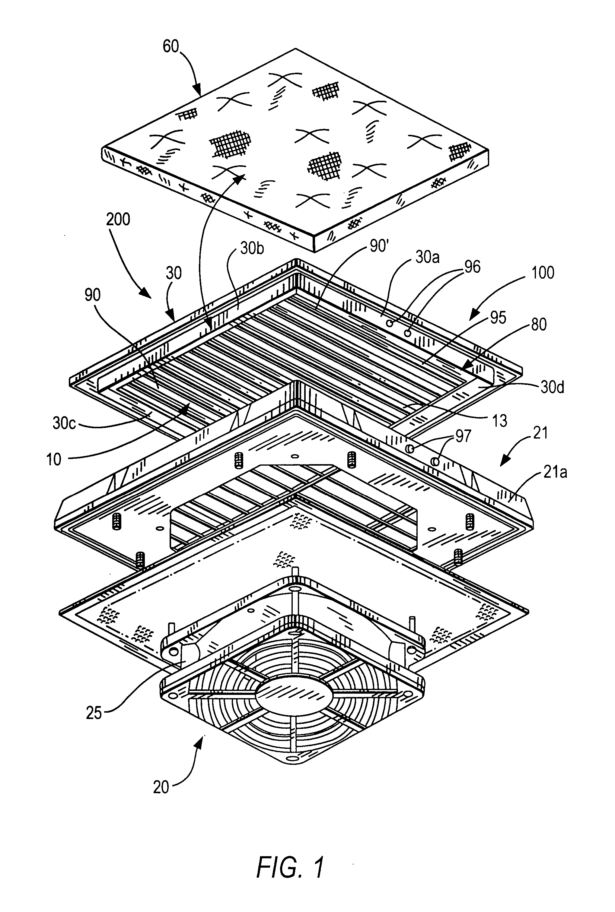
[0062] The air passage device 200 illustrated in FIG. 1 to 3 of the invention is able to be used in connection with a fan or ventilator as a filter fan and without a fan 20 as an outlet filter. The air passage device 200 is used in housings of components generating waste heat, such as switch boxes, electronics boxes, computer systems or suchlike, in which the air passage device 200 is incorporated in mounting openings 50 in a wall 51 of such a housing (FIG. 3).

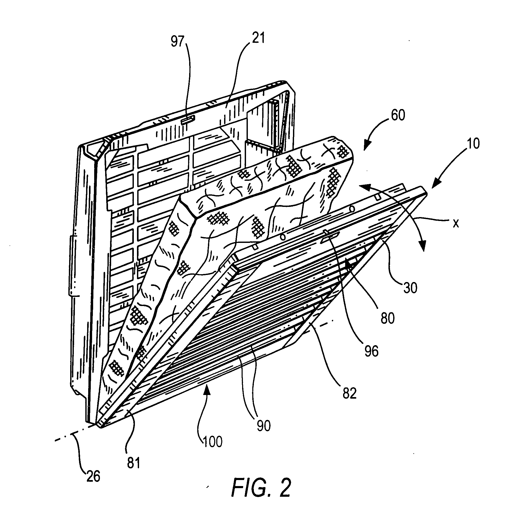
[0063] The essential components of the air passage device 200 are a design cover 80 with a fan grid 10 with ventilation slits, which forms the front covering device 100 for a base housing 21, a fan support 25 for the fan 20, when the air passage device 200 is used as a filter fan (FIG. 1 to 3).

[0064] The covering device 100, which forms the fan grid 10, is constructed as a design cover 80 and consists of a frame-like housing 30, preferably with side walls 30a, 30b, 30c, 30d and with sheet elements 90, in which ventilation sli...

second embodiment

[0072] The air passage device 200 of the invention, illustrated in FIG. 10 to 12, is able to be used in connection with a fan or ventilator as a filter fan, and without a fan 20 as an outlet filter. The air passage device 200 is used in housings of components generating waste heat, such as switch boxes, electronics boxes, computer systems or suchlike, in which the air passage device 200 is installed in mounting openings 50 in a wall 51 of such a housing (FIG. 12).

[0073] The essential components of the air passage device 200 are a design cover 280 with a fan grid 210 with ventilation slits, which forms the front covering device 100 for a base housing 221 and a fan support 25 for the fan 20, when the air passage device 200 is used as a filter fan (FIG. 10 to 12).

[0074] The covering device 100, which forms the fan grid 210, is constructed as design cover 280 and consists of a frame 230 with side walls 230a, 230b, 230c, 230d and in the embodiment illustrated in the drawing with sheet e...


PUM

PropertyMeasurementUnit
Timeaaaaaaaaaa
Timeaaaaaaaaaa
Timeaaaaaaaaaa

Abstract

An air passage device for installation into a mounting opening (50) in a wall (51) for components generating waste heat, such as a switch box, includes a base housing (21; 221) with a fan support (25) and a design cover (80; 280), wherein the design cover (80; 280) has on an air inlet side a covering device (100) constructed as a fan grid (10; 210) with sheet elements (90, 90′; 290, 290′). At least one swivellable sheet element (90) or at least one flexible, tongue-shaped side wall section (235), separated from the remaining side wall surface by slits (332, 333) running transversely to the longitudinal direction of the side wall, is formed in the region of the upper side wall of the design cover (80; 280) facing away from the swivel axis (26; 226) for swivelling the design cover (80; 280), wherein the sheet element (90) and the tongue-shaped side wall section (235) are formed between the design cover (80; 280) and the base housing (21; 221) as a detachable and lockable detent connection (40; 240), that can be operated by a finger.

Description

BACKGROUND OF THE INVENTION [0001] 1. Field of the Invention [0002] The present invention relates to an air passage device, particularly a filter fan or outlet filter. [0003] 2. Description of the Related Art [0004] In the case of components arranged in a housing, which generate corresponding waste heat, it is necessary to carry off the waste heat from the housing and control a temperature in the housing by blowing in or drawing off ambient air into the interior of the housing to a greater or lesser extent by means of the fan. Computer housings are a known example of this. Usually, such housings are provided with a filter fan which either runs continuously or is switched on and off by a control arrangement, depending on a temperature in the housing. The filter fan is arranged in a recess of a wall of the housing and is fixed for example by means of screw connections. At the same time, corresponding air outlet slits are provided for the outlet of air at another location in the housin...

Claims


Application Information

Patent Timeline
IPC IPC(8): H05K5/00
CPCF04D29/646F04D29/703B01D46/0005F24F2001/0096H05K7/20181F24F13/085F24F1/0071F24F1/0073
Inventor PFANNENBERG, ANDREAS
Owner PFANNENBERG GMBH
Why Eureka
Try Eureka