Control Apparatus for Occupant Restraint Device

a technology for controlling apparatus and occupants, which is applied in the direction of process control, process control, pedestrian/occupant safety arrangement, etc., can solve the problems of extremely difficult to completely inhibit the breakage of the wire harness using this type of wiring structur

Inactive Publication Date: 2008-02-21
BOSCH CORP
View PDF0 Cites 10 Cited by
  • Summary
  • Abstract
  • Description
  • Claims
  • Application Information

AI Technical Summary

Benefits of technology

[0005] An object of the invention is to provide a control apparatus for an occupant restraint device that can be expected to operate with a high degree of reliability.
[0006] Another object of the invention is to provide a control apparatus for an occupant restraint device that allows control of an occupant restraint device to be performed without any malfunctions even if an output line of a sensor is broken.

Problems solved by technology

However, there is a problem that is liable to occur, namely, that if the output wire of the satellite sensor is broken during the collision of the vehicle, the output signal from the satellite sensor can not finally be received by the control unit.
However, there are various different types of collision, and thus it is extremely difficult to completely inhibit breakage of the wire harness using this type of wiring structure.

Method used


Image

  • Control Apparatus for Occupant Restraint Device
  • Control Apparatus for Occupant Restraint Device
  • Control Apparatus for Occupant Restraint Device

Examples


Embodiment Construction

[0011] In order to provide a more detailed explanation of the invention, a description will be given of the invention while referring to the appended drawings.

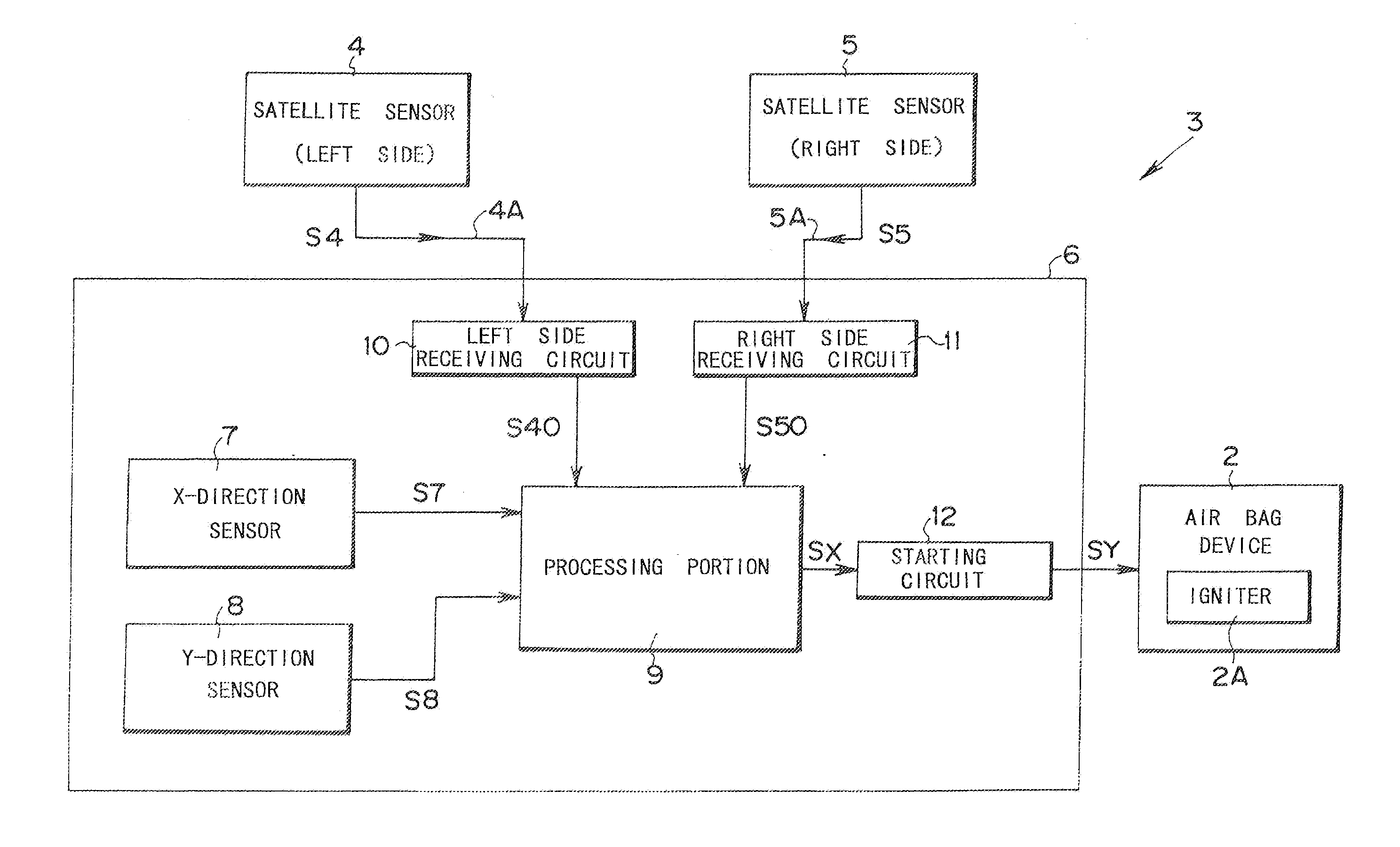
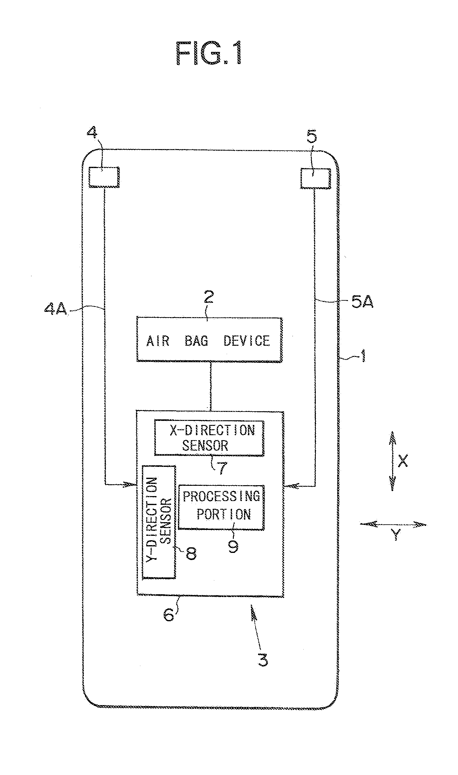
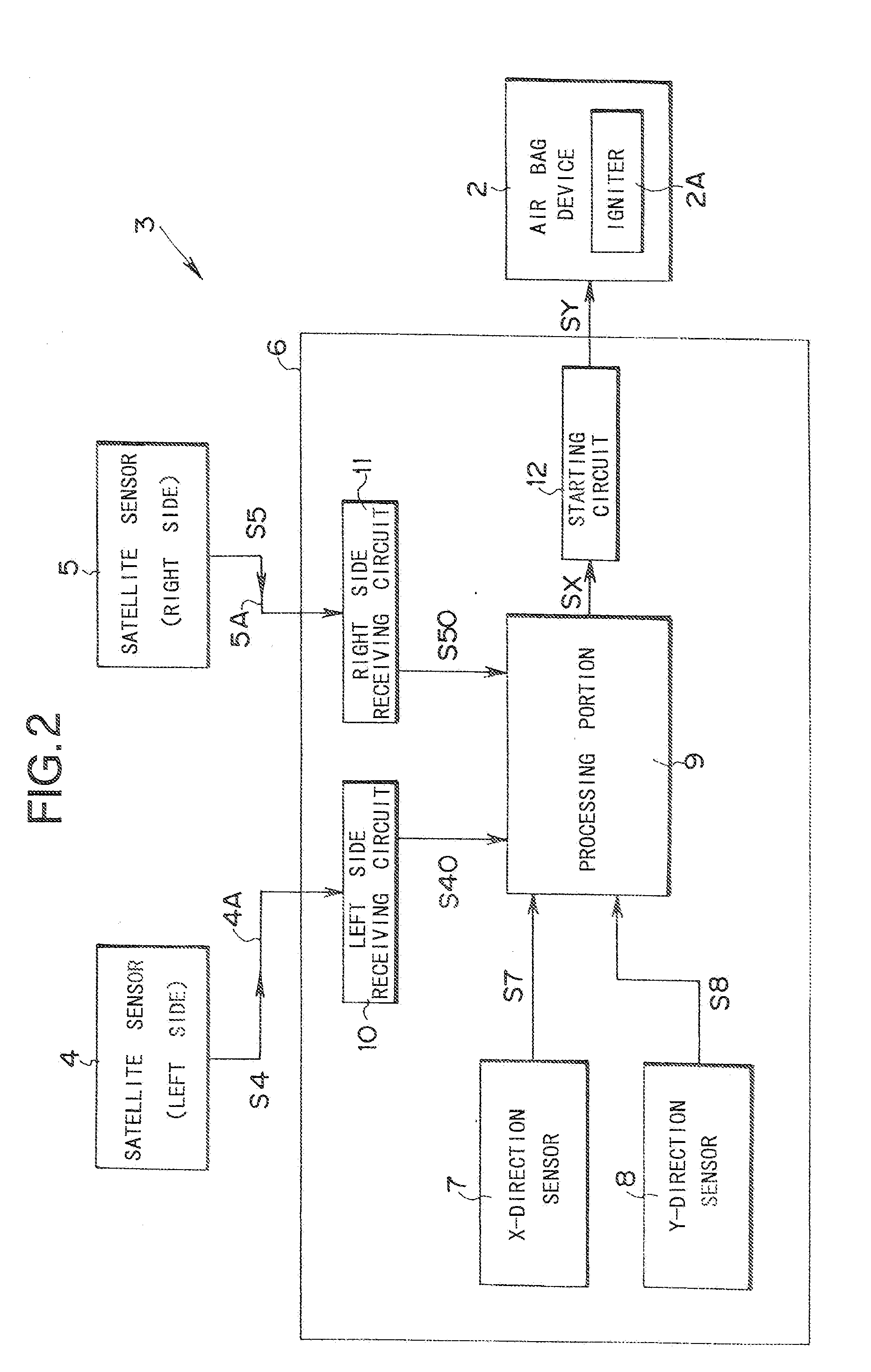
[0012]FIG. 1 is a schematic view of the structure of an embodiment of the invention. In FIG. 1 reference numeral, 1 is a vehicle, 2 is an air bag device mounted in the vehicle 1 in order to protect an occupant of the vehicle 1 from shock that occurs as a result of a collision of the vehicle 1. The reference numeral 3 indicates, as a whole, a control apparatus for controlling the operation of the air bag device 2 that is an occupant restraint device.

[0013] The control apparatus 3 includes satellite sensors 4, 5 provided in an impact zone in a front section of the vehicle 1, and a control unit 6. The control unit 6 is positioned in proximity to a central section of the vehicle 1. The term of impact zone as used here indicates a section of the body of the vehicle 1 that is anticipated to deform when the vehicle 1 has a collisio...


PUM


Abstract

Based on respective output signals (S4, S5, S7, S8) satellite sensors (4, 5) provided in an impact zone of a front section of a vehicle (1); an X-direction sensor (7) that detects an impact acceleration of the vehicle in a traveling direction thereof; a Y-direction sensor (8) that detects an impact acceleration in a direction that is orthogonal to the traveling direction, a control unit (6) that controls the operation of an air bag device (2) includes: a selection output portion that fetches, from among output signals (S40, S50) from the satellite sensors (4, 5) and an output signal (S80) from the Y-direction sensor (8), the output signal with the higher value; and a determination portion (9) that performs a collision determination of the vehicle (1) in response to the output signal (S7) from the X-direction sensor (7). A level of a threshold value used for the collision determination performed by the determination portion (9) is set based on the output signal selected by the selection output portion. In the case that the output signals (S4, S5) from the satellite sensors (4, 5) cannot be obtained, the level of the threshold value used for the collision determination is set based on the output signal (S80) from the Y-direction sensor (8), thereby allowing the operation of the collision determination to be maintained appropriately.

Description

TECHNICAL FIELD [0001] The present invention relates to a control apparatus for an occupant restraint device like an air bag. BACKGROUND ART [0002] In order to control an occupant restraint device that protects an occupant of a vehicle from the shock that occurs when there is a collision, control apparatuses with various different structures have been proposed. These control apparatuses include sensors for collision detection in each section of the vehicle, and control the operation of the occupant restraint device based on processed signals from the sensors. JPA-2001-310692 discloses an example of this type of control apparatus. In this type of known structure, a satellite sensor for collision detection is positioned in a crush zone in a front section of the vehicle. As a result, if the vehicle has a collision, shock caused by the collision that occurs in the front section of the vehicle can be detected as rapidly as possible, thereby allowing the occupant restraint device to be op...

Claims


Application Information

Patent Timeline
Patent Type & Authority Applications(United States)
IPC IPC(8): B60R21/01B60R21/16
CPCB60R21/0132B60R21/0136B60R21/16B60R2021/01211B60R2021/01325B60R2021/01345
Inventor HAYASHI, TAISUKESAYNISCH, IVORMIYAGUCHI, KOICHIMATSUI, EIICHIRO
Owner BOSCH CORP
Why Eureka
Try Eureka