
Line Diagnostic Device, Bus System, Line Diagnostic Method, Bus System Control Method, and Line Diagnostic Program

Inactive Publication Date: 2008-02-21
HITACHI LTD +1
View PDF6 Cites 27 Cited by
  • Summary
  • Abstract
  • Description
  • Claims
  • Application Information

AI Technical Summary

Benefits of technology

[0026] To increase the diagnosis rate of a control device itself, the present invention does not rely on a technology for diagnosing the bus, which is a data transfer path, and on the diagnosis by a microprocessor but provides an external diagnostic device having the arbiter function diagnosis means to cause this device to safely stop the output of data when an arbiter abnormality is detected.
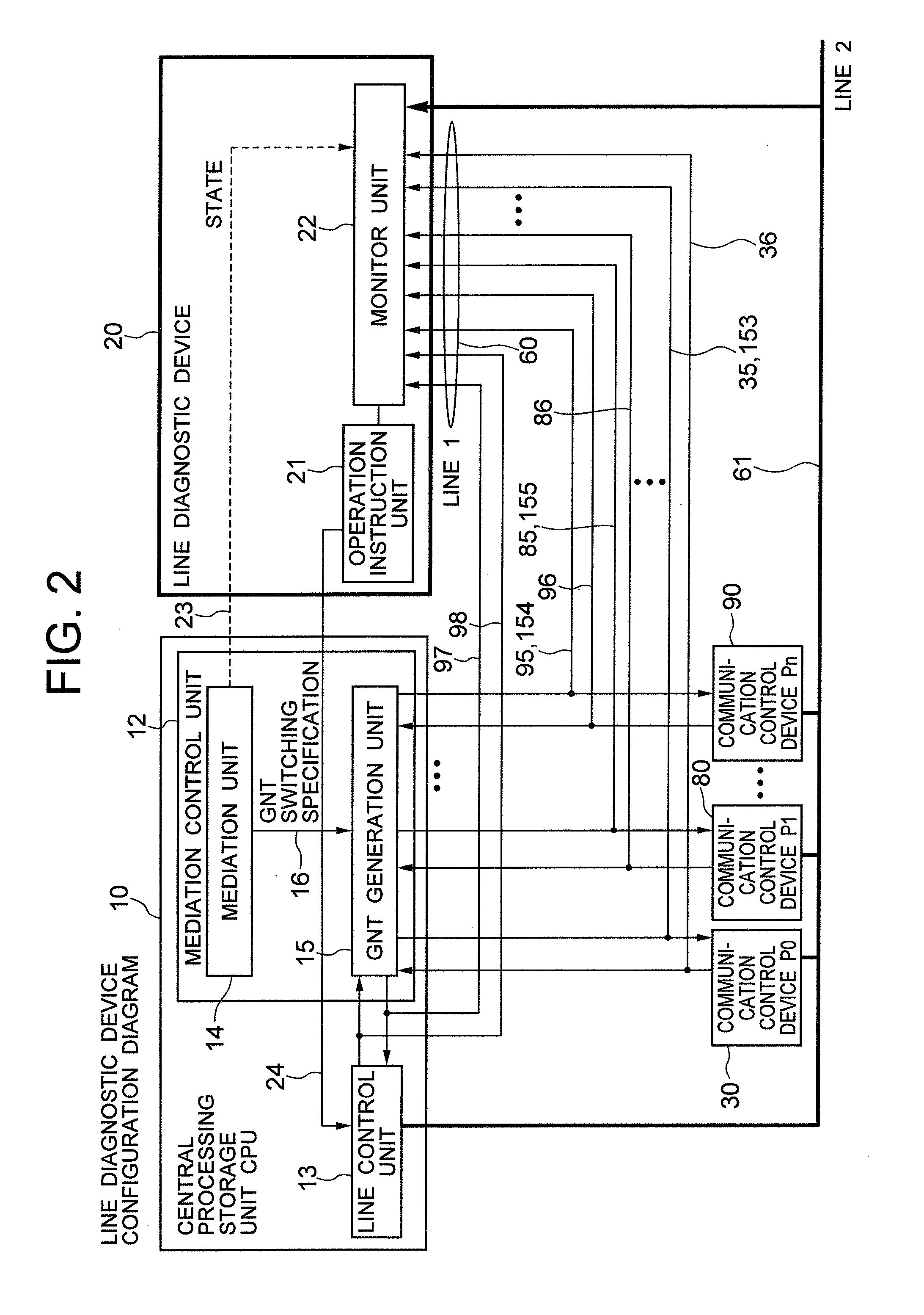
[0028] The diagnostic device monitors the signals in the mediation period before the bus transfer cycle during the online operation. As described above, to solve the problem of performance degradation involved in the software-based arbiter operation diagnosis, the diagnostic device performs hardware-based monitoring in the mediation period to prevent the data transfer from being interrupted. Monitoring the output status of the bus right grant GNT signal in the monitoring time period makes it possible to detect whether the arbiter operation is normal or abnormal. Normally, the effective bus right grant signal should not be output during the mediation period to multiple bus masters. If the bus right grant signal is issued to multiple bus masters, it is possible that a signal sticking condition occurs or a bus right grant GNT signal generation unit in the arbiter fails. In this case, the diagnostic device can monitor the bus right grant GNT signal to diagnose the arbiter function. If multiple bus right grant GNT signals are output, multiple bus masters, which incorrectly identify that they have received the bus right, may output data to the bus with the result that a data conflict may occur. Such a situation, if generated while safety data is being transferred, destroys the safety data. Therefore, the diagnostic device has means that, when this abnormality is detected, protects the safety data immediately and outputs a stop instruction to the bus control unit to stop the data safely.
[0035] The present invention satisfies the requirements for the responsiveness and for the safety of data transfer and mediation control operation without decreasing the transfer performance, thus increasing the safety of the whole control device. More specifically, the diagnostic device, configured by a part different from the arbiter, provides means for monitoring the timing of data transfer during an online operation for diagnosing an arbiter operation abnormality, not through software diagnostic processing, but on a hardware basis. This diagnostic device satisfies the requirement for the responsiveness of data transfer and for the safety of the mediation control operation without performance degradation due to a failure in the data transfer on the line, thus increasing the safety of the whole control device.
[0036] The present invention provides bus switches between the bus and the masters and between the bus and slaves and, during the transfer of first data, disconnects the master and the slave, not related to the transfer, from the bus. This configuration reduces failures generated in the transfer of data on the bus.
[0037] This configuration implements a reliable bus system that reliably transfers priority data simply by adding low-cost improvements to an existing bus system without duplicating the bus and the circuits.

Problems solved by technology

If the bus right grant signal is issued to multiple bus masters, it is possible that a signal sticking condition occurs or a bus right grant GNT signal generation unit in the arbiter fails.
If multiple bus right grant GNT signals are output, multiple bus masters, which incorrectly identify that they have received the bus right, may output data to the bus with the result that a data conflict may occur.
Such a situation, if generated while safety data is being transferred, destroys the safety data.

Method used


Image

  • Line Diagnostic Device, Bus System, Line Diagnostic Method, Bus System Control Method, and Line Diagnostic Program
  • Line Diagnostic Device, Bus System, Line Diagnostic Method, Bus System Control Method, and Line Diagnostic Program
  • Line Diagnostic Device, Bus System, Line Diagnostic Method, Bus System Control Method, and Line Diagnostic Program

Examples


first embodiment

Description of First Embodiment

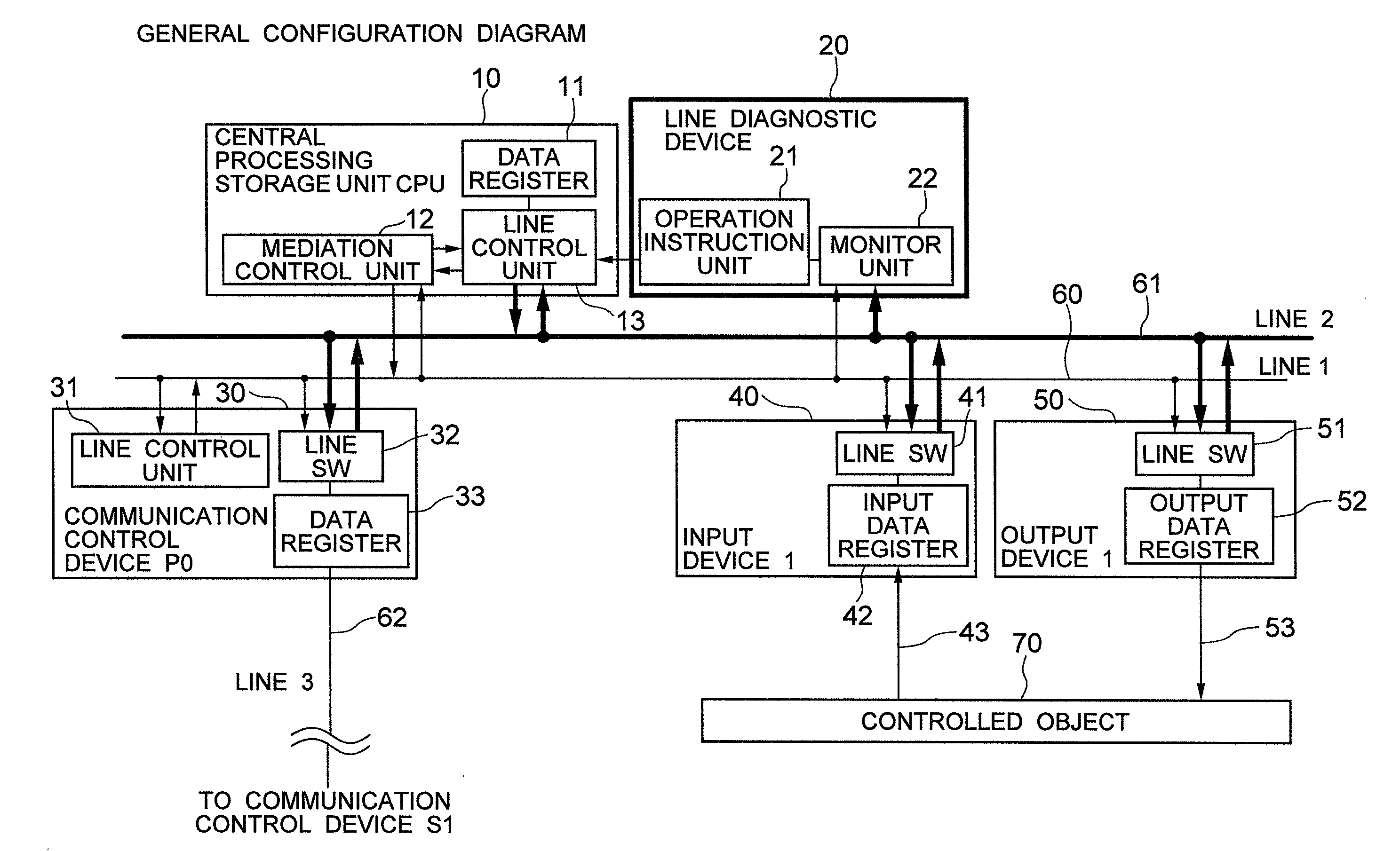
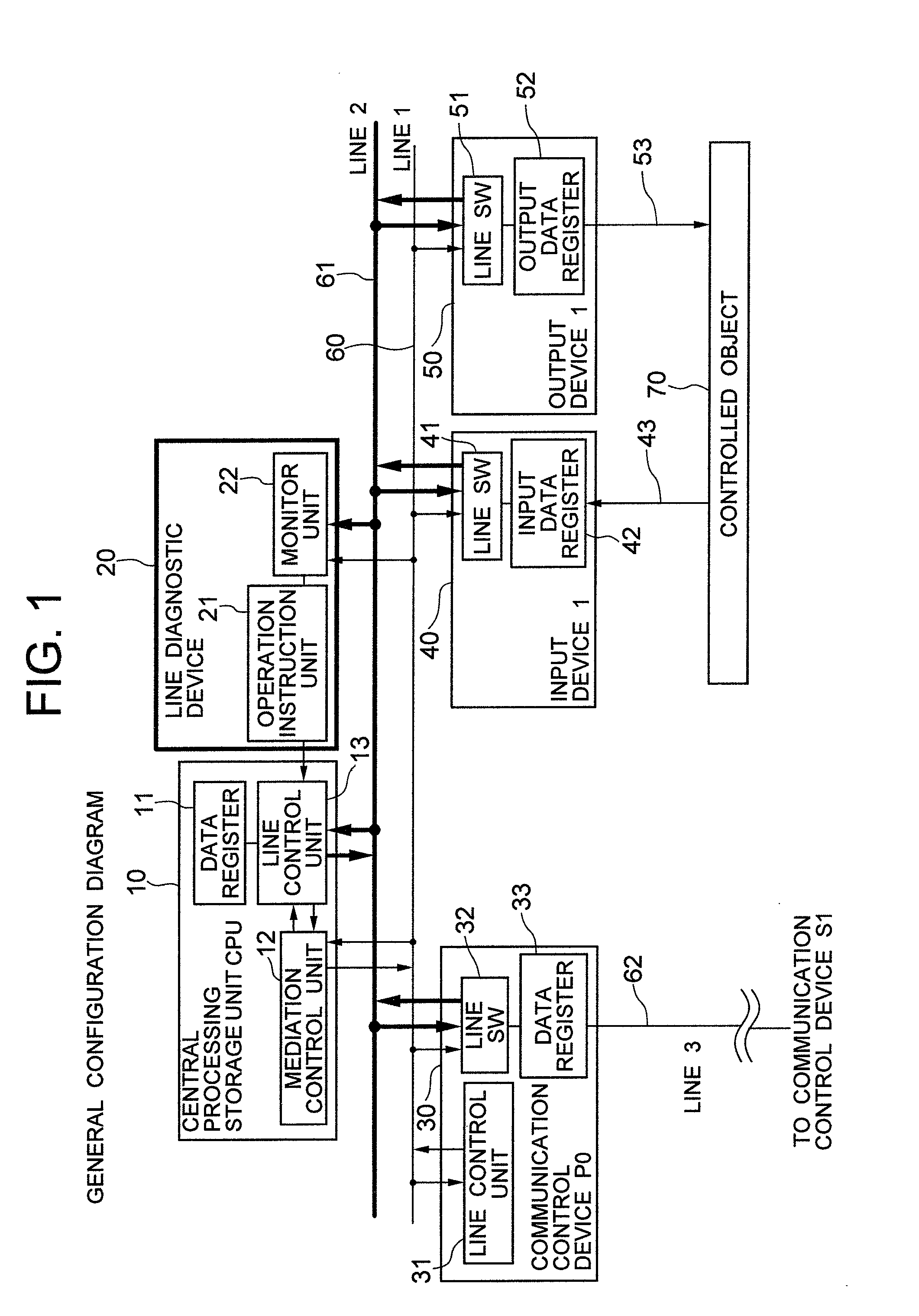
[0082]FIG. 5 and FIG. 6 show the failure mode and the abnormal operation of the mediation control unit, monitored and detected by the line diagnostic device, and one solution applied when an abnormality is detected. The description of FIG. 3 refers to the possibility of a data conflict that may occur when the line usage right grant signal GNT is issued from the mediation control unit 12 to two or more devices. The monitor unit 22 in the line diagnostic device comprises means for monitoring and detecting this failure mode. FIG. 5 shows the flow of diagnosis of the line diagnostic device 20 performed when the line usage right grant signal GNT is issued to two or more devices, and FIG. 6 is a timing diagram showing the operation performed when the GNT signal is issued to two or more devices as well as an example of a solution.

[0083]FIG. 5 shows the abnormality detection means, one of the means included in the line diagnostic device 20, for detecting an a...

second embodiment

Description of Second Embodiment

[0086]FIG. 7 and FIG. 8 show the failure mode and the abnormal operation of the mediation control unit, monitored and detected by the line diagnostic device, and another action that is taken when an abnormality is detected. FIG. 7 shows the diagnostic flow that is executed when a line diagnostic device 20 works as means for detecting an abnormality in the switch control signal. FIG. 8 shows the diagnostic flow that is executed when the line diagnostic device 20 works as means for detecting an abnormality in the line usage right grant signal GNT.

[0087] Referring to FIG. 7, a monitor unit 22 in a mediation control unit 12 has a bus SW output status CHK unit 26. The bus SW output status CHK unit 26 monitors the line 160 and the line 261. If the safety data transfer status signal, which is a part of the signals output by the central processing storage unit CPU 10 or the communication control device P030, indicates that “safety data is being transferred”,...

third embodiment

Description of Third Embodiment

[0091]FIG. 9 shows the failure mode and the abnormal operation of the mediation control unit, monitored and detected by the line diagnostic device, and another action that is taken when an abnormality is detected. FIG. 9 shows the diagnostic flow that is executed when a line diagnostic device20 works as abnormality detection means for detecting an abnormality in the state transition in the mediation control unit 12.

[0092] Referring to FIG. 9, the monitor unit 22 in the mediation control unit 12 has a state transition CHK unit 28. The state transition CHK unit 28 monitors a mediation state transition STATE signal 23 output by the mediation control unit 12, the line 160, and the line 261. The state transition CHK unit 28 checks the validity of the state transition sequence of the mediation state transition STATE signal 23.

[0093] The state transition during the normal operation executed by the mediation unit 14 of the mediation control unit 12 shown in ...


PUM


Abstract

A control device diagnoses the operation of a bus arbiter that mediates bus usage requests output by multiple devices in the control device to satisfy both responsiveness and safety. A diagnostic module, implemented as an external diagnostic module, monitors signals related to the arbiter mediation and, if an abnormality caused by a signal sticking condition or an abnormality in a mediation control unit is detected, stops data transfer safely to prevent safety data from being output incorrectly.

Description

BACKGROUND OF THE INVENTION [0001] 1. Field of the Invention [0002] The present invention relates to a line diagnostic device, a bus system, a line diagnostic method, a bus system control method, and a line diagnostic program, and more particularly to a line diagnostic device, a bus system, a line diagnostic method, a bus system control method, and a line diagnostic program that are suitable for ensuring safety. [0003] 2. Description of Related Art [0004] Recent advances in the bus arbiter technology for mediating competition for mastership on the common bus are remarkable. Especially, the data transfer speed of a common bus used for a PC system, such as a PCI bus or an ISA bus, is rapidly increasing and, to guarantee the operation of the system, a bus arbiter for mediating multiple bus masters is required. [0005] The operation of the bus arbiter is executed by mediation means that selects one bus master from multiple bus masters, each of which issues a bus usage right request, and ...

Claims


Application Information

Patent Timeline
IPC IPC(8): G06F3/00
CPCG06F11/364
Inventor KOBAYASHI, EIJIBANDOU, AKIRAKOBAYASHI, MASAMITSUSHIRAISHI, MASAHIROONOZUKA, AKIHIROUMEHARA, TAKASHIKOKURA, SHINISHIKAWA, MASAKAZUFURUTA, YASUYUKIFUNAKI, SATORUSEKI, YUUSUKEOOTANI, TATSUYUKISAKATA, TERUAKISHIMAMURA, KOTARO
Owner HITACHI LTD
Learn More