Multi stage pressure regulator

a pressure regulator and multi-stage technology, applied in the field of pressure regulators, can solve the problem that pressure regulators are typically not suitable for fuel cell system applications, and achieve the effect of high flow ra

Inactive Publication Date: 2008-02-28
GM GLOBAL TECH OPERATIONS LLC
View PDF12 Cites 49 Cited by
  • Summary
  • Abstract
  • Description
  • Claims
  • Application Information

AI Technical Summary

Benefits of technology

[0019]FIG. 9 is a cross sectional view of the pressure regulator illustrated in FIG. 8, showing the valve heads positioned for relatively low flow rates;...

Problems solved by technology

Such pressure regulators are typically not suitable for fuel cell system applications because of the a...

Method used


Image

  • Multi stage pressure regulator
  • Multi stage pressure regulator
  • Multi stage pressure regulator

Examples


Embodiment Construction

[0021]The following detailed description and appended drawings describe and illustrate various exemplary embodiments of the invention. The description and drawings serve to enable one skilled in the art to make and use the invention, and are not intended to limit the scope of the invention in any manner.

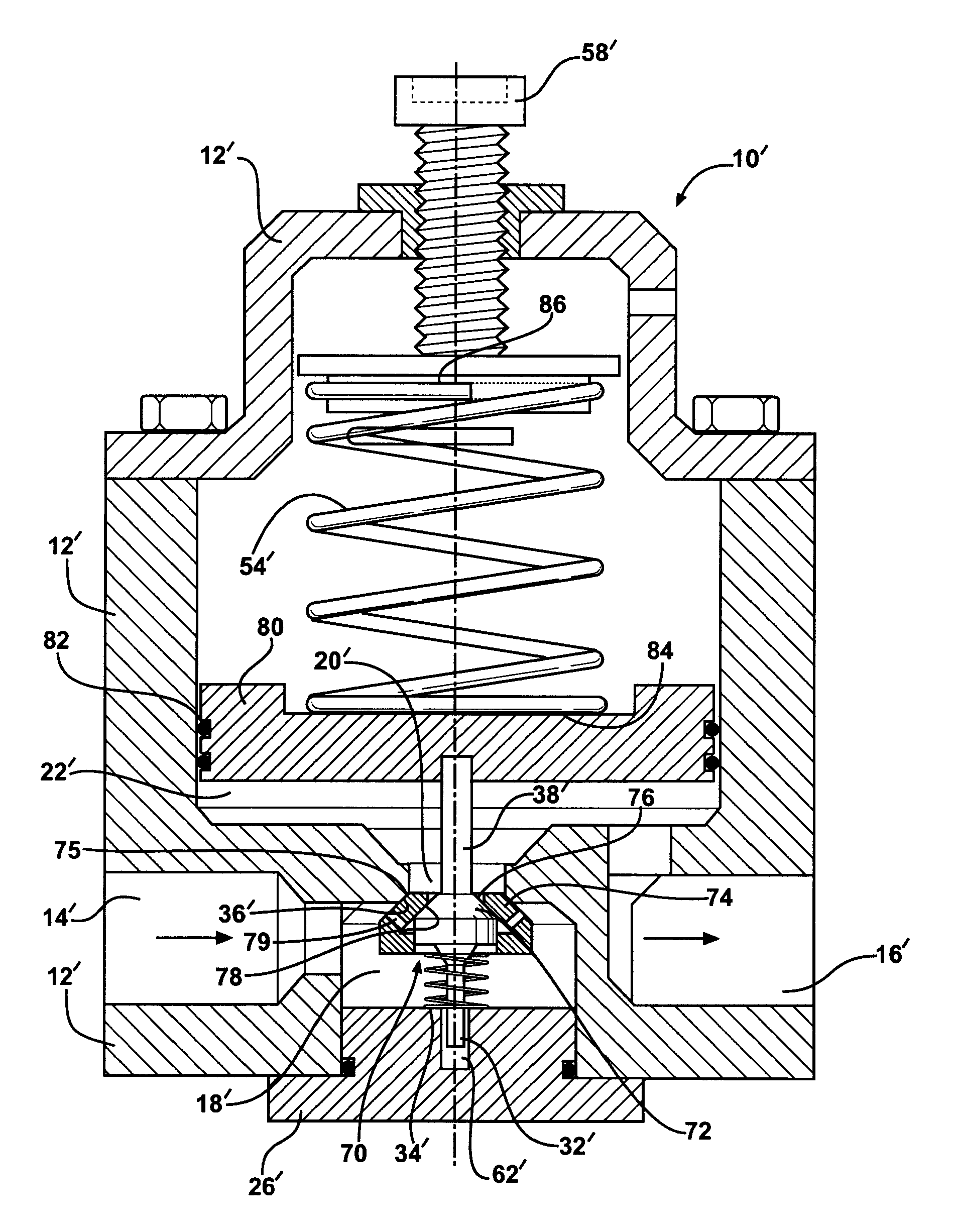
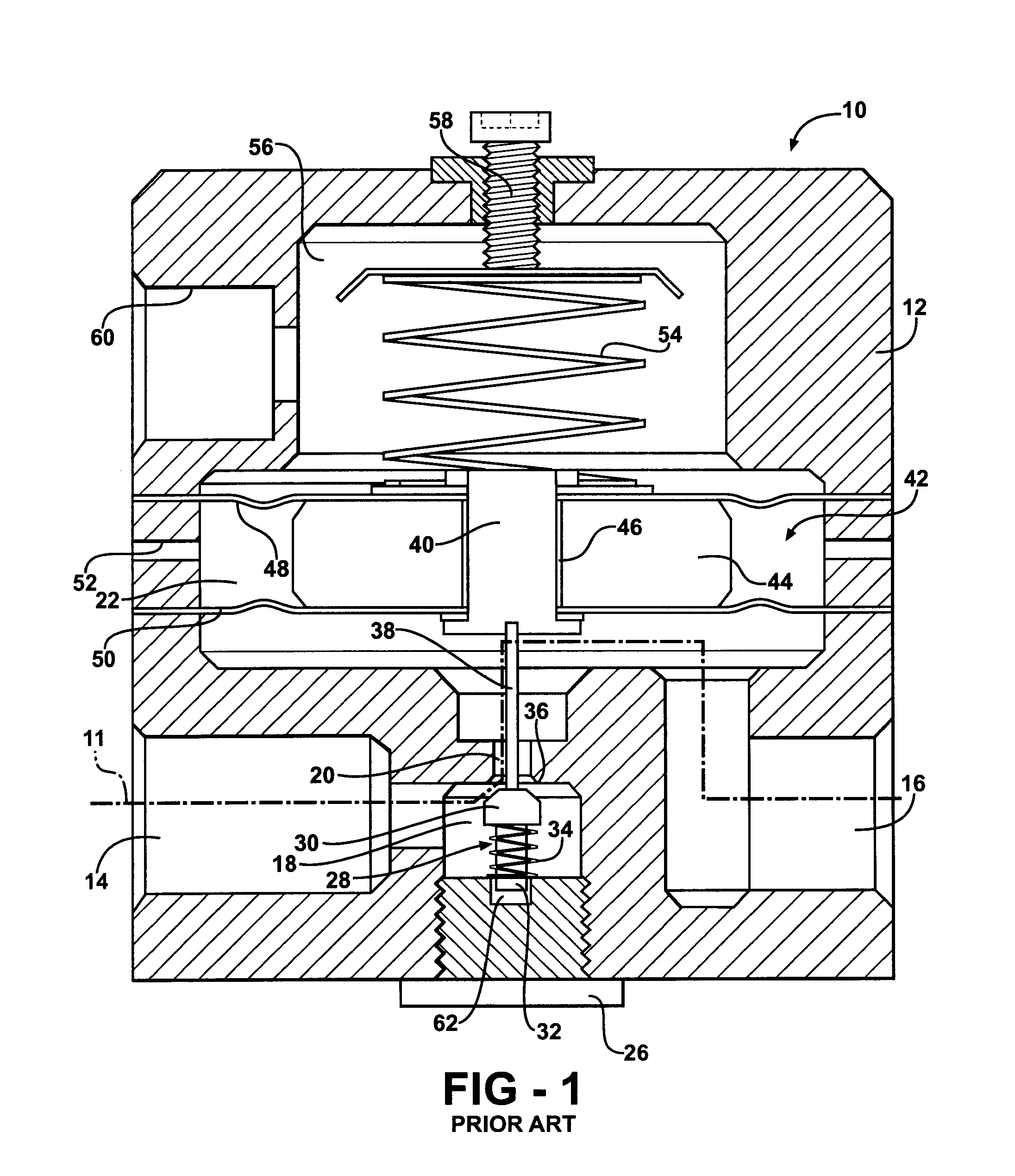
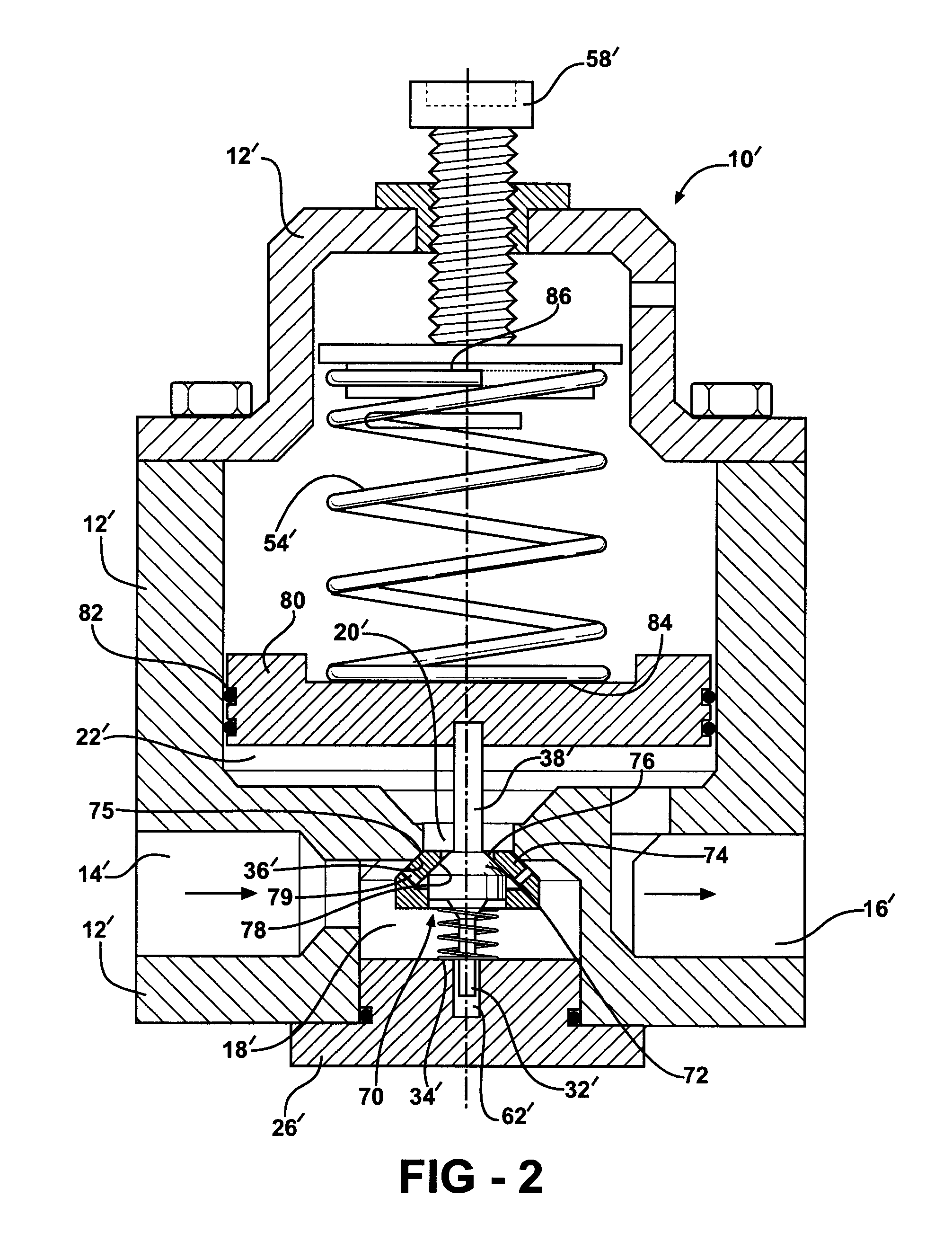
[0022]FIG. 1 shows a known pressure regulator 10 having regulator body 12. A fluid flows into an inlet port 14 and exits the regulator 10 at an outlet port 16. As used herein, the term fluid refers to a liquid, gas, or any combination thereof. The fluid flows along a flow path 11 through the inlet port 14 to a first chamber 18, through an orifice 20, and into a second chamber 22. The second chamber 22 is in fluid communication with the outlet port 16.

[0023]The flow of the fluid from the inlet port 14 to the outlet port 16 is controlled by a valve 28 positioned within the first chamber 18. The valve 28 includes a valve head 30, a valve body 32, and a valve spring 34 disposed around th...


PUM


Abstract

A pressure regulator is disclosed wherein multiple valve stages are used to accommodate low flow rates and to maximize a turn-down ratio of the regulator.

Description

FIELD OF THE INVENTION[0001]The invention relates to a pressure regulator and, more particularly, to a pressure regulator that includes multiple valve stages to maximize a performance thereof during low flow rate operation and to maximize a turn-down ratio of the regulator.BACKGROUND OF THE INVENTION[0002]A hydrogen fuel cell is an electro-chemical device that includes an anode and a cathode with an electrolyte therebetween. The anode receives a fuel such as hydrogen gas and the cathode receives a fluid such as oxygen or air. Several fuel cells are typically combined in a fuel cell stack to generate a desired amount of power. A typical fuel cell stack for a vehicle may include several hundred individual cells. Typically, the fluid is caused to flow through the stack by a compressor. Oxygen not consumed in the stack is expelled as a cathode exhaust gas that may include water as a stack by-product.[0003]Pressure regulators are employed in fuel cell systems at various locations to cont...

Claims


Application Information

Patent Timeline
IPC IPC(8): F16K31/12
CPCG05D16/10G05D16/107G05D16/109Y10T137/7795Y10T137/7825Y10T137/7826Y10T137/8704Y10T137/87378
Inventor PECHTOLD, RAINER
Owner GM GLOBAL TECH OPERATIONS LLC
Why Eureka
Try Eureka