Combination heat exchanger having an improved end tank assembly

a heat exchanger and end tank technology, applied in the direction of heat exchanger sealing arrangement, stationary conduit assembly, lighting and heating apparatus, etc., can solve the problems of increased vehicle weight, increased system complexity, manufacturing cost, failure of structural integrity in transverse partitions, etc., to achieve greater compression ratio of gaskets on the exterior edges of bulkheads

Inactive Publication Date: 2008-02-28
MAHLE INT GMBH
View PDF14 Cites 42 Cited by
  • Summary
  • Abstract
  • Description
  • Claims
  • Application Information

AI Technical Summary

Benefits of technology

[0014]The header plate has a stage portion with latitudinal pockets to cooperate with the exterior edges of the bulkheads to define a first spatial distance with respect to the gasket therein. The header plate also has an annular planar surface to cooperate with the perimeter edge of the end tank to define a second spatial distance with respect to the gasket therein. The first spatial distance is less than the second spatial distance, thereby resulting in a greater compression ratio of the gasket located within the first spatial distance relative to the compression ratio of the gasket located within the second spatial distance. More specifically, the compression ratio of the gasket on the exterior edges of the bulkhead is greater than the compression ratio of the gasket on the perimeter edge of the end tank.
[0015]The greater compression ratio of the gasket between the exterior edges of the bulkheads and lateral pockets of the header plate allows for a more robust seal between chambers. Robust seals are required along bulkheads to withstand stresses resulting from expansion differential between chambers within an end tank of a combination heat exchanger that houses heat transfer fluids with different temperature and pressure cycle requirements.

Problems solved by technology

A major draw back of stacking radiators is a decrease of heat transfer efficiency due to the increased pressure drop through the stack of radiators.
There are other drawbacks of utilizing multiple radiators such as increase in vehicle weight, systems complexity, and manufacturing cost.
Utilizing a combination radiator to dissipate heat from multiple heat transfer fluids having different thermal and pressure cycle requirements may result in failure of structural integrity in transverse partitions 40a, 40b.
Due to excessive stress, transverse partition 40a may fail thereby allowing the heat transfer fluids to intermingle resulting in potential damage to the heat sources being cooled.
Furthermore, transverse partitions 40a, 40b does not offer a significant thermal barrier between the two different heat transfer fluids thereby resulting in decrease efficiency of heat dissipation of the cooler heat source.

Method used


Image

  • Combination heat exchanger having an improved end tank assembly
  • Combination heat exchanger having an improved end tank assembly
  • Combination heat exchanger having an improved end tank assembly

Examples


Embodiment Construction

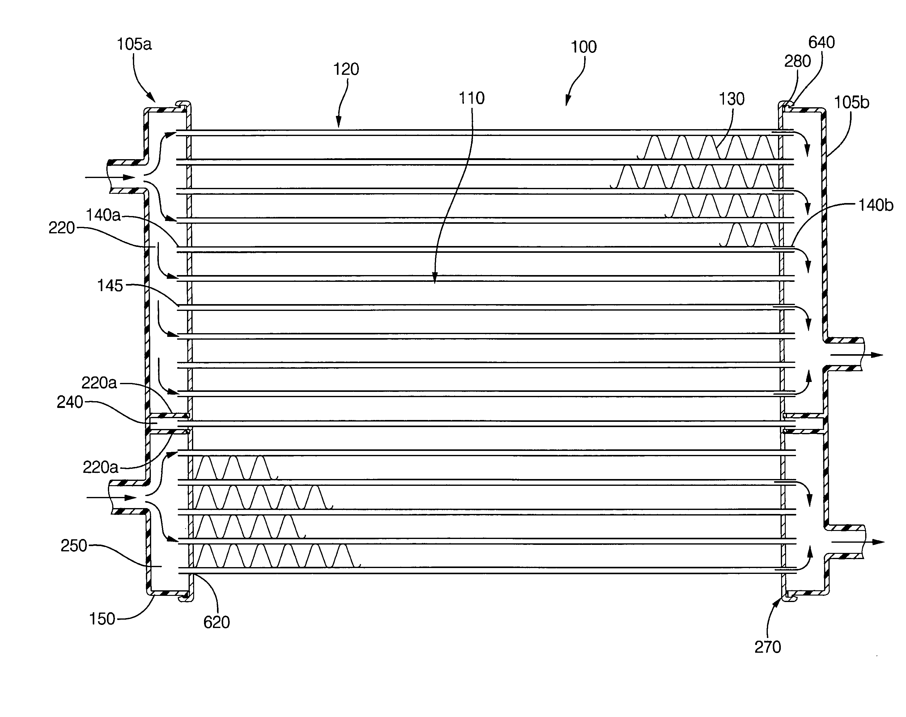
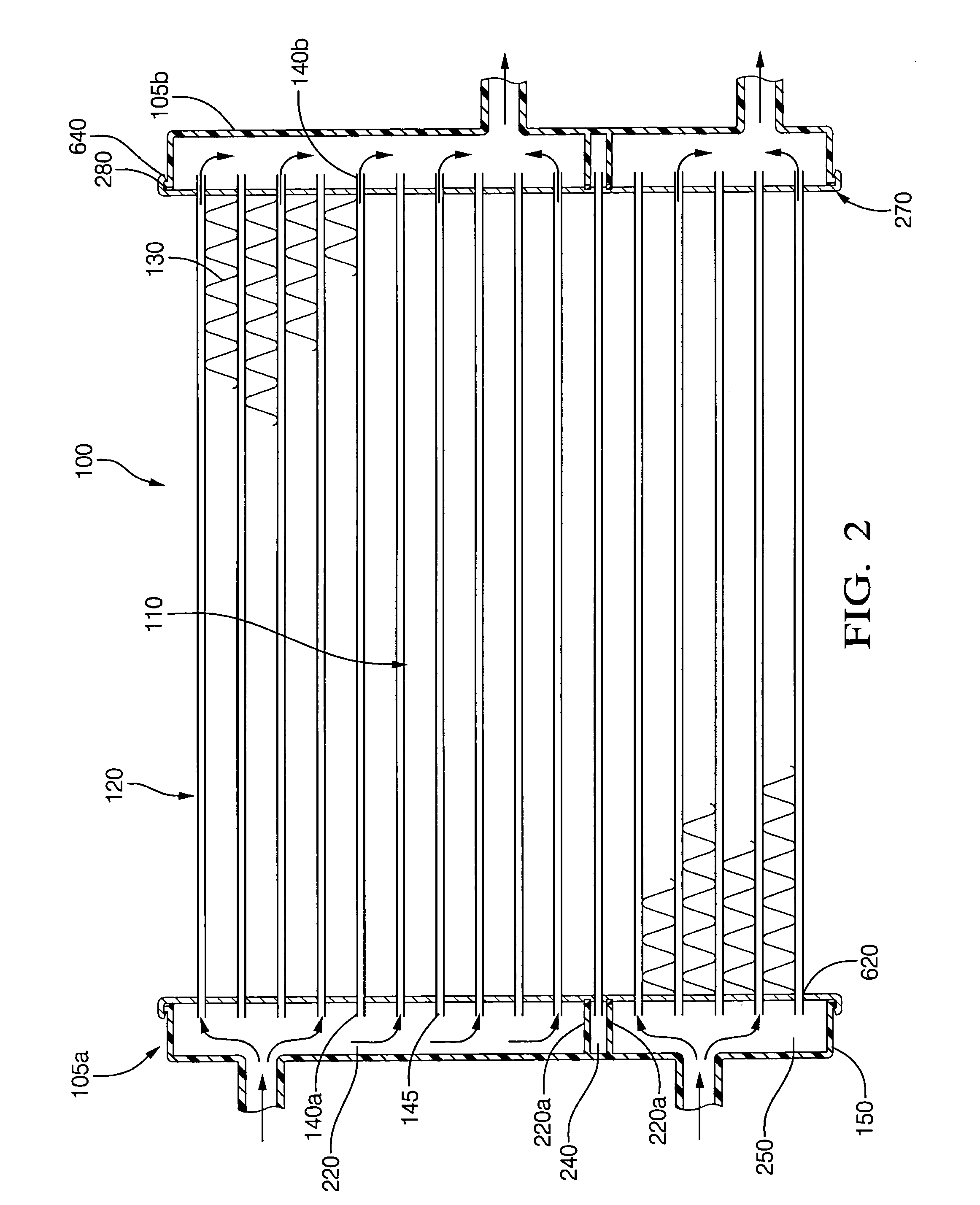
[0026]In reference to FIGS. 2 through 8, end tank 150 is shown substantially rectangular in appearance. The present invention does not intend the substantially rectangular shape to be limiting, but can also encompass other elongated shapes with an open face along the longitudinal axis.

[0027]FIG. 2 is a cross-sectional view of the present invention combination heat exchanger. The heat exchanger includes a core 110 having a bundle of tubes 120 that are substantially parallel. The tubes 120 are jointed longitudinally by conventional means such as welding, brazing or soldering to a supporting structure such as fins between the tubes. The core 110 has two core ends 140a, 140b corresponding with tube openings 145.

[0028]Each core end is attached to end tank assembly 105 that comprises of end tank 150, a gasket 280, and a header plate 270. The tube openings 145 are affixed to perforations 620 located on the header plate 270 by conventional means such as welding, brazing or soldering. Header...


PUM


Abstract

A combination heat exchanger comprising of a heat exchange core having a plurality tubes, wherein the core having at least one core end; an end tank having two side walls and two end walls, two bulkheads the cavity defining a least a first chamber, a second chamber, and a third chamber, a perimeter edge defined by exterior edges of said side walls, exterior edges of said two end walls, and exterior edges of said two bulkheads; a header plate engaged between said end tank and said core end; and a gasket between said perimeter edge and contact surface of said header plate, wherein the compression ratio of the gasket is varied along the contact surfaces of the perimeter edge and contact surface of the end plate.

Description

TECHNICAL FIELD OF INVENTION[0001]The invention relates to a combination heat exchanger, for a motor vehicle, having an end tank assembly that includes an integrated plastic tank mated to a metal header with an improved gasket therebetween; more particularly, where the improved gasket is formed of cure-in-place elastomer having varying compression ratios.BACKGROUND OF INVENTION[0002]Radiators are commonly used in automobiles having an internal combustion engine to convey heat away from hot engine components to the cooler ambient air. A radiator is part of a closed loop system wherein the radiator is hydraulically connected to passageways within an engine through which a heat transfer fluid, such as a mixture of water and ethylene glycol, is circulated.[0003]A typical radiator is formed of a central core having a multitude of parallel tubes with fins therebetween to increase the surface area for optimal heat dissipation. Hydraulically attached to either end of the core that correspon...

Claims


Application Information

Patent Timeline
Patent Type & Authority Applications(United States)
IPC IPC(8): F28F11/00
CPCF28D1/0443F28F2270/02F28F9/0226F28F9/0209
Inventor LEITCH, FRANK JOSEPHCOYLE, BRIAN J.GMEREK, ROBERT CHARLES
Owner MAHLE INT GMBH
Why Eureka
Try Eureka