Range-finding sensor, and electronic device equipped with range-finding sensor

a range-finding sensor and electronic device technology, applied in the field of range-finding sensors, can solve the problems of complex manufacturing process of range-finding sensors and the inability to accurately perform range-finding, and achieve the effect of reducing the size of an electronic devi

Inactive Publication Date: 2008-02-28
SHARP KK
View PDF3 Cites 50 Cited by
  • Summary
  • Abstract
  • Description
  • Claims
  • Application Information

AI Technical Summary

Benefits of technology

[0044]With this configuration, it is possible realize a reduction in the size of an electronic apparatus equipped with a range-finding sensor.

Problems solved by technology

However, because a process of applying the translucent filter 128 is necessary, the manufacturing process of those range-finding sensors is complicated.
Thus accurate range-finding cannot be performed.

Method used


Image

  • Range-finding sensor, and electronic device equipped with range-finding sensor
  • Range-finding sensor, and electronic device equipped with range-finding sensor
  • Range-finding sensor, and electronic device equipped with range-finding sensor

Examples


first embodiment

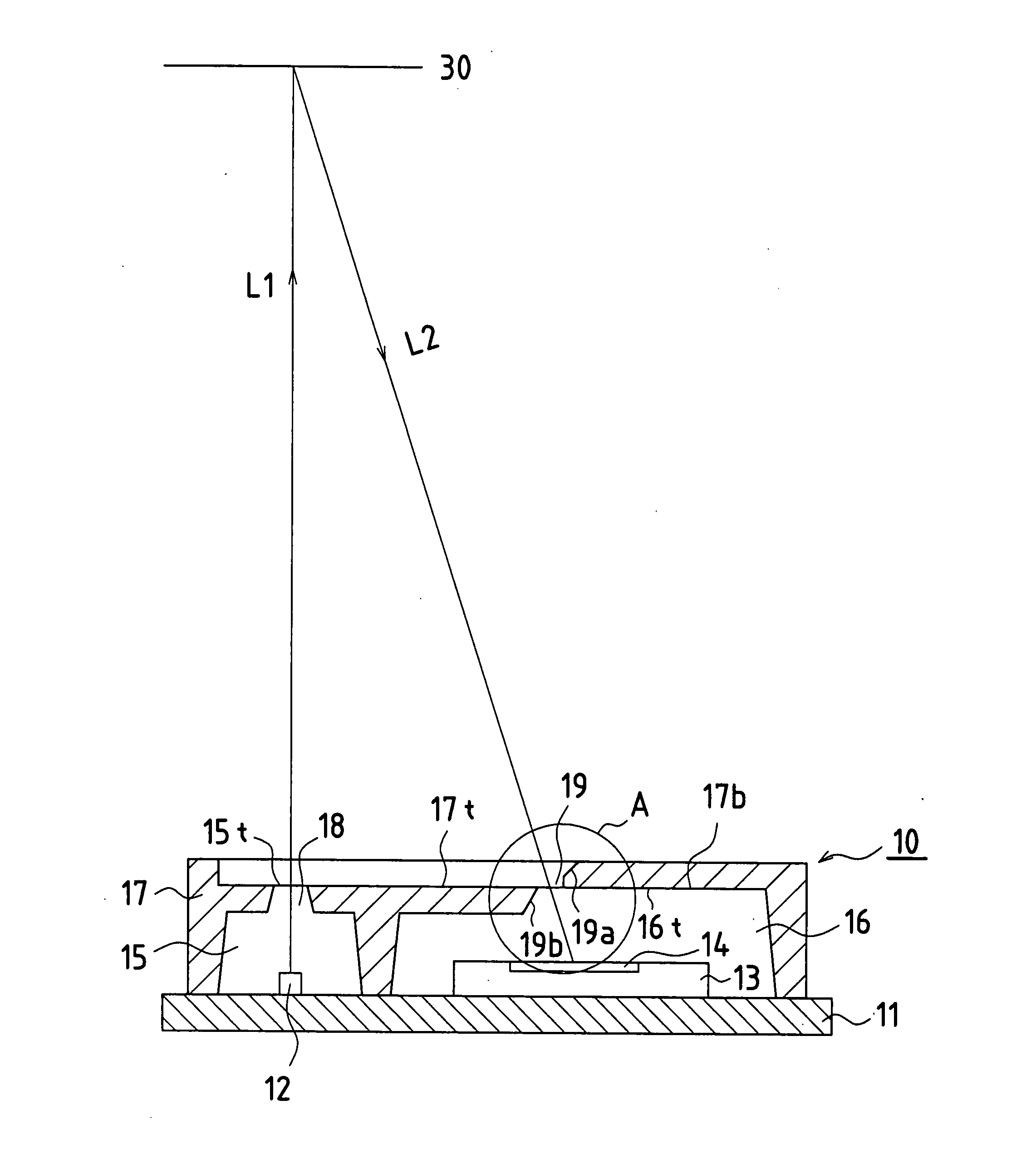
[0053]FIG. 1 illustrates the structure of a range-finding sensor according to Embodiment 1 of the invention and a distance measuring principle thereof. A cross-sectional view of a range-finding sensor 10 is shown in FIG. 1. Hatching is omitted from the cross-section of a light-emitting element 12, a light-receiving element 13, and translucent resin sealing portions 15 and 16.

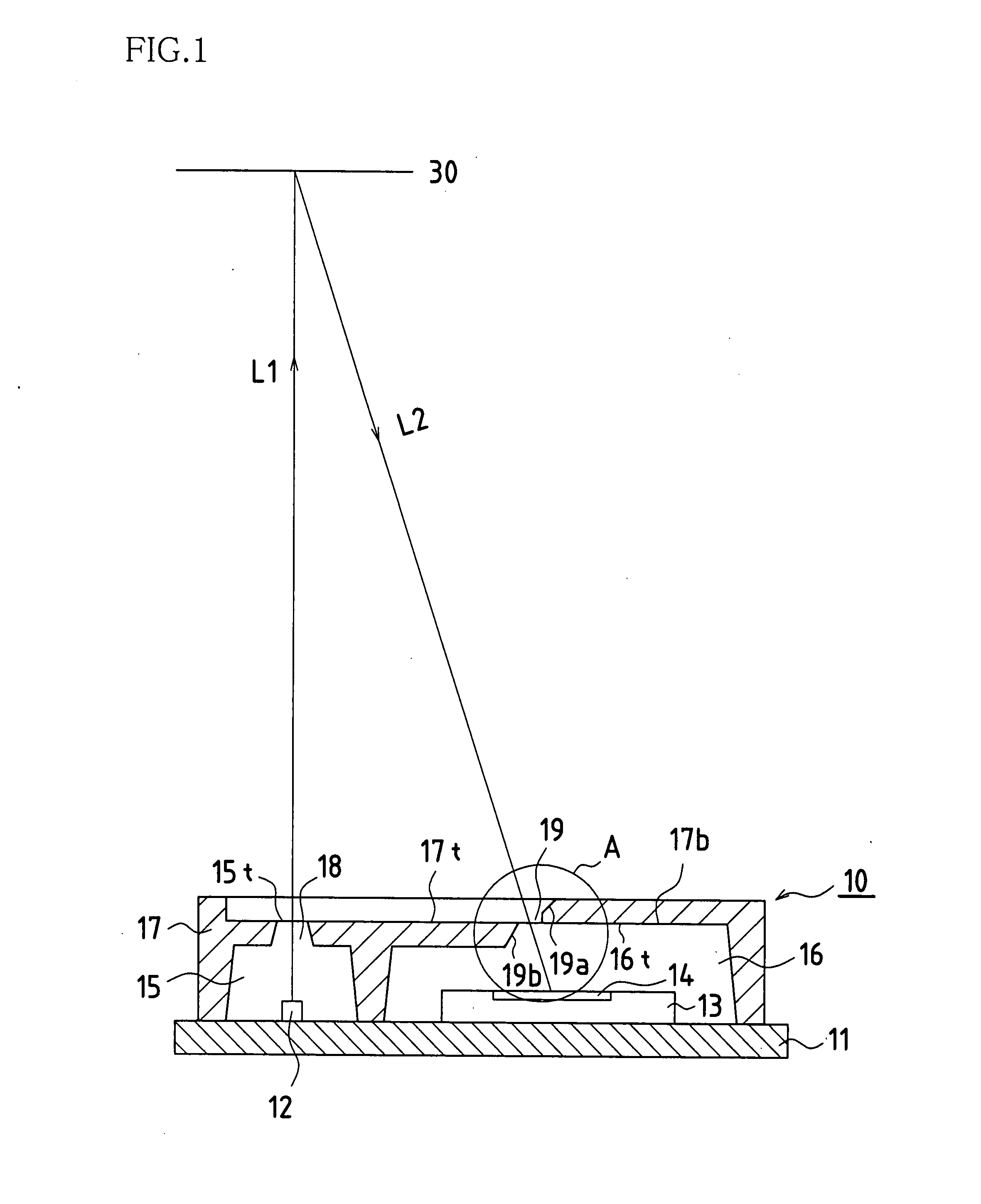
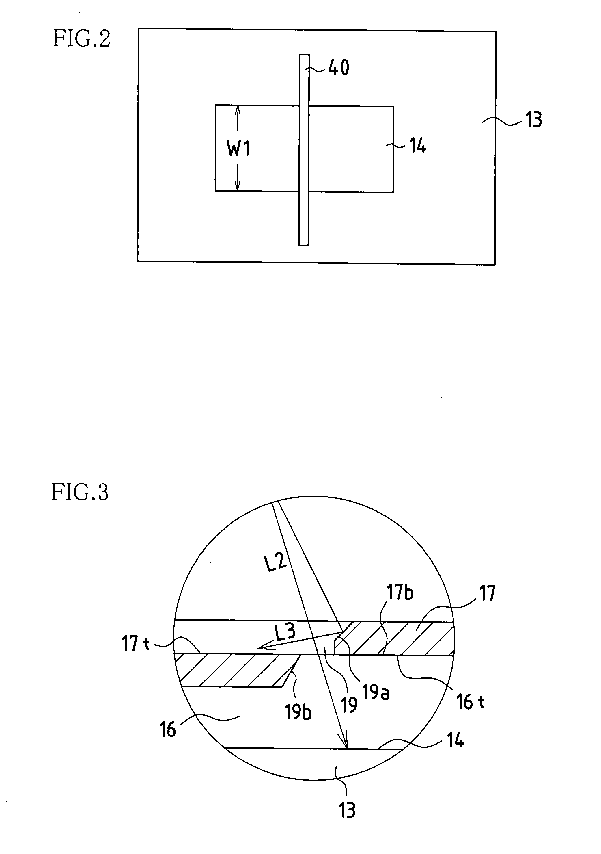
[0054]FIG. 2 is a plan view in which the light-receiving element portion in FIG. 1 is viewed from the side of a light-receiving portion slit, and illustrates a state in which light has been condensed on a light-receiving face of the light-receiving element. FIG. 3 is a partial enlarged view of portion A in FIG. 1, and illustrates a light path of reflected light reflected by a range-finding subject.

[0055]The range-finding sensor 10 according to the present embodiment is configured with a substrate 11, the light-emitting element 12 and the light-receiving element 13 disposed on the upper face (reference face) of t...

embodiment 2

[0077]An electronic device (not shown) according to the present embodiment is equipped with a range-finding sensor according to Embodiment 1. Because this electronic device is equipped with a small and highly precise range-finding sensor, the electronic device is small and has high precision.


PUM


Abstract

In one embodiment of the range-finding sensor of the invention, a light-emitting element that projects light to a range-finding subject, and a light-receiving element that receives reflected light reflected by the range-finding subject, are disposed on a reference face, and the light-emitting element and the light-receiving element are each individually sealed with resin by a translucent resin sealing portion. Further, the outer circumference of the translucent resin sealing portion is covered by an opaque resin sealing portion, and the opaque resin sealing portion is provided with a light-emitting portion slit that constricts the luminous flux of light projected to the range-finding subject, and a light-receiving portion slit that constricts the luminous flux of reflected light reflected by the range-finding subject.

Description

[0001]This application claims priority under 35 U.S.C. § 119(a) on Japanese Patent Application No. 2006-230724 filed in Japan on Aug. 28, 2006, the entire contents of which are hereby incorporated by reference.BACKGROUND OF THE INVENTION[0002]1. Field of the Invention[0003]The present invention relates to a range-finding sensor that employs a triangular range-finding system and detects the distance to a range-finding subject, the range-finding sensor being provided with a light-emitting element that projects light to the range-finding subject and a light-receiving element that receives light reflected by the range-finding subject.[0004]2. Description of the Related Art[0005]In the conventional technology, range-finding sensors are known that employ a triangular range-finding system and detect the distance to a range-finding subject by projecting light to the range-finding subject and receiving light reflected by the range-finding subject.[0006]FIG. 4 illustrates a distance-measuring...

Claims


Application Information

Patent Timeline
Patent Type & Authority Applications(United States)
IPC IPC(8): G01B11/00
CPCG01C3/085G01B11/026
Inventor TAKAOKA, TAKASHI
Owner SHARP KK
Why Eureka
Try Eureka