Routing failure recovery mechanism for network systems

a network system and failure recovery technology, applied in the field of communication path multiple failure recovery system, can solve the problems of processor canceling switching, communication is disconnected, and each network unit cannot know the state of each segmen

Inactive Publication Date: 2008-02-28
HITACHI LTD
View PDF5 Cites 37 Cited by
  • Summary
  • Abstract
  • Description
  • Claims
  • Application Information

AI Technical Summary

Benefits of technology

[0008]According to the present invention, therefore, each network unit can know the state of each segment in the communication path and can switch the current communication path to another no matter where the failure occurs in the upward direction or in the downward direction.

Problems solved by technology

This results in disconnection of the communication and this has been a problem (first problem).
Consequently, each network unit cannot know the state of each segment in the subject communication path.
This has also been a problem (second problem).
However, if the communication path is already switched or being switched in the downward segment, the processor cancels the switching.

Method used


Image

  • Routing failure recovery mechanism for network systems
  • Routing failure recovery mechanism for network systems
  • Routing failure recovery mechanism for network systems

Examples


first embodiment

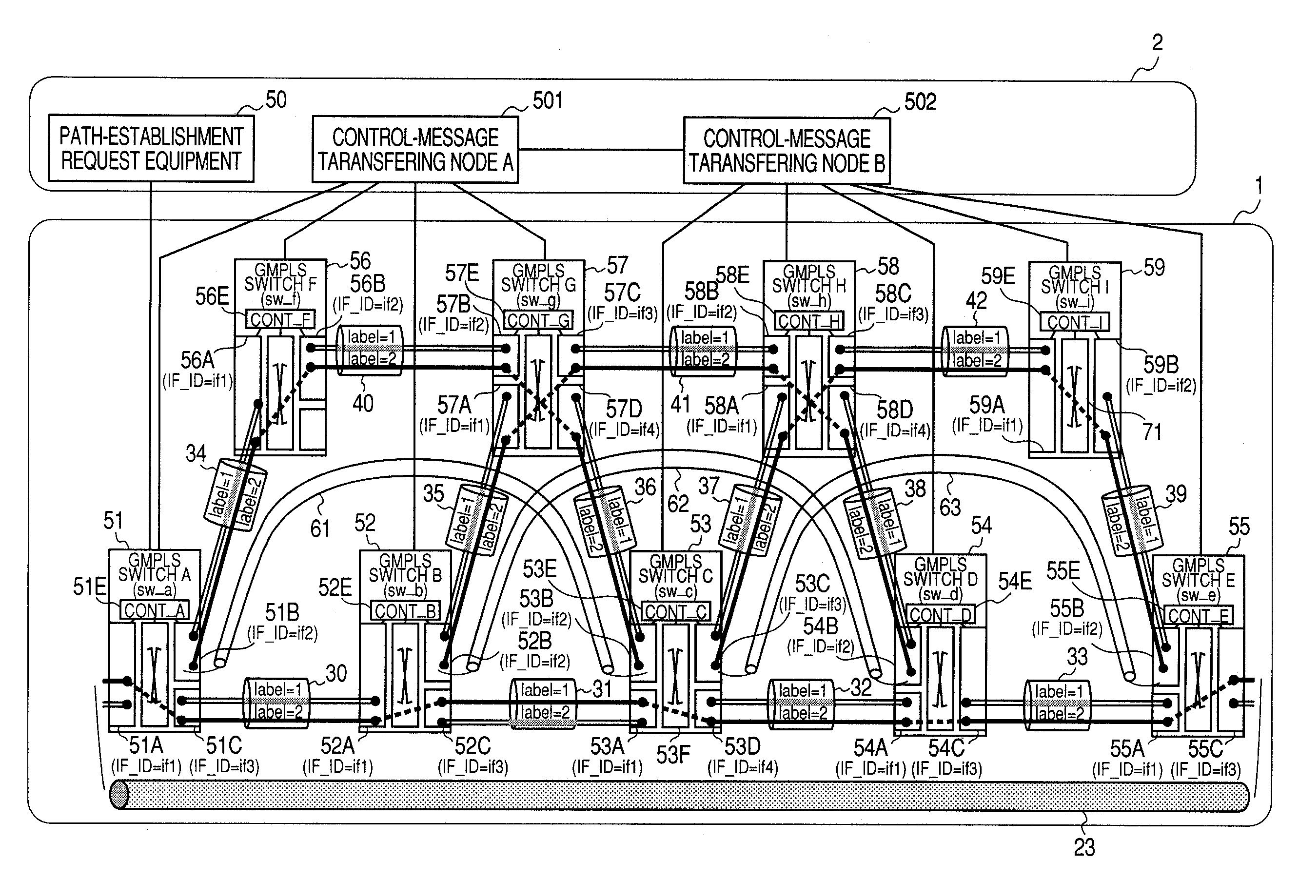
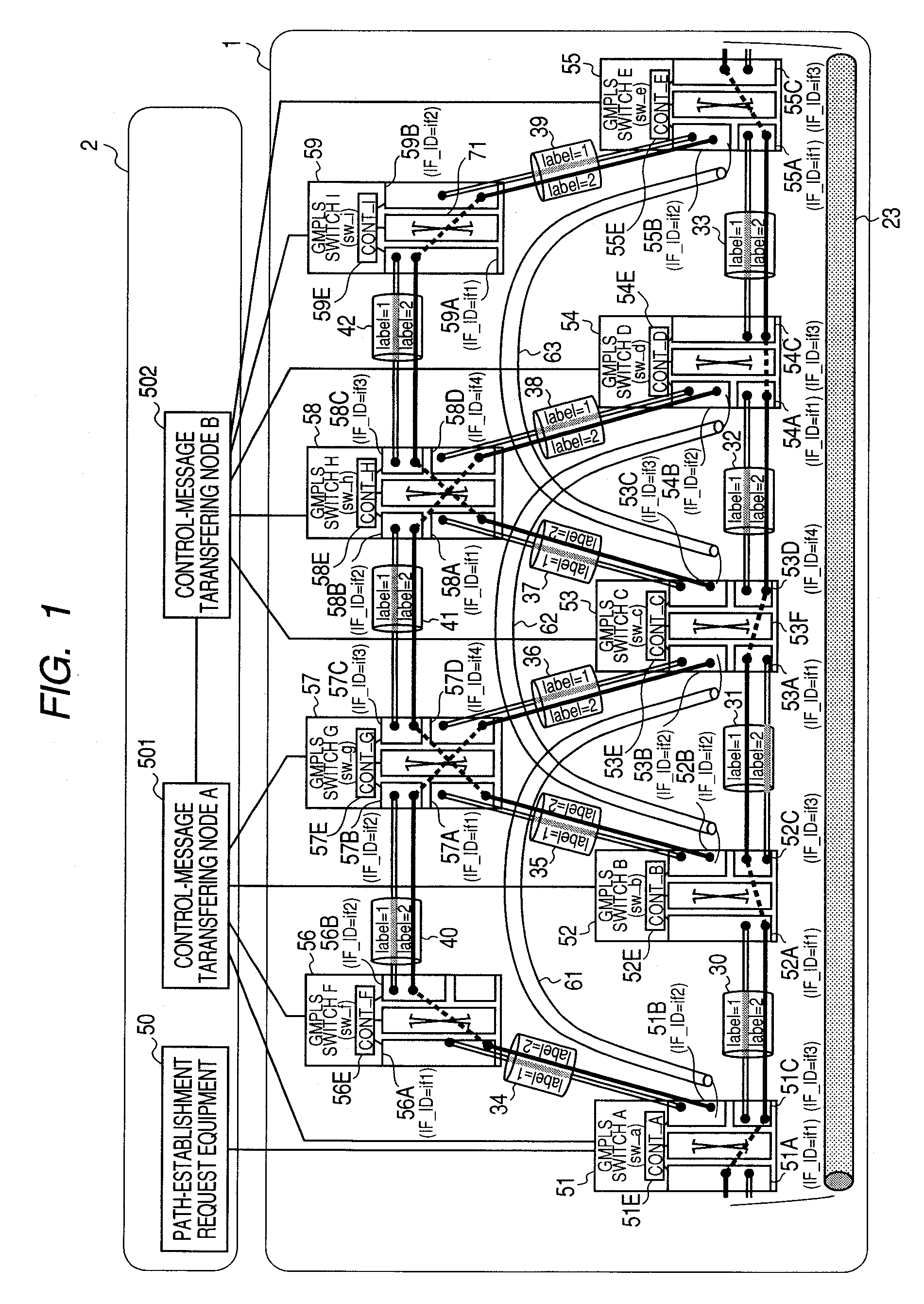
[0066]At first, a description will be made for a configuration of a communication network system in a first embodiment of the present invention with reference to FIG. 1.

[0067]A network 1 shown in FIG. 1 consists of a plurality of network units 51 to 59 connected to each another through transmission lines 30 to 42. In this first embodiment, the network 1, which consists of 9 network units and 13 transmission lines, may be set freely for the number of network units and the topology. In addition, each transmission line between network units is enabled for bidirectional communications, but the transmission line can be substituted for optical fibers to be used as a pair of transmission media for upstream and downstream communications.

[0068]Each of the communication paths 61 to 63 is established upon starting exchanges of GMPLS generalized RSVP-TE messages among the network units 51 to 59 through a control message transferring network 2. In this first embodiment, 3 2-hop communication pat...

second embodiment

[0280]Next, a second embodiment of the present invention will be described.

[0281]In the first embodiment described above, the GMPLS generalized RSVP-TE is used as a signaling program. However, the present invention can also use another protocol such as the GMPLS CR-LDP, or the like.

[0282]FIG. 30 shows a message format used by a network system in this second embodiment of the present invention.

[0283]Just like the network system in the first embodiment, the network system in this second embodiment uses a segment generalized object for each RESV message to enable segment information to be notified among network units.

[0284]In FIG. 9 of the first embodiment, each object is defined individually. In FIG. 30 of this second embodiment, each segment is stored in the same container. Each of the containers (2503 to 2504) includes items of segment ID (25031), segment's starting point node information (25032), and segment's ending point node information (25033).

[0285]A container includes primary...


PUM


Abstract

A network unit for exchanging control messages with a remote network unit through a communication path to be established in a network. The network unit enables recovery of failures whether they occur in any of one way links, both-way links. The network unit also enables recovery of node failures to occur in a GMPLS network. The network decides whether or not it is possible to bypass all failure-occurred links detected in the communication path by switching the communication path to another by itself. When it is possible, the network unit detects the switching state of a downward segment that can bypass all those failure-occurred links. If the communication path is already switched or being switched in the downward segment, the network unit cancels the switching. If the communication path is not switched nor being switched in the downward segment, the network unit switches the communication path to a bypass route.

Description

CLAIM OF PRIORITY[0001]The present application claims priority from Japanese application JP 2006-226720 filed on Aug. 23, 2006, the content of which is hereby incorporated by reference into this application.FIELD OF THE INVENTION[0002]The present invention relates to a communication path multiple failure recovery system to be used in a communication network for establishing a communication path with use of a signaling protocol.BACKGROUND OF THE INVENTION[0003]There are some techniques used for controlling a communication path in a communication network respectively. One of them is, for example, the GMPLS (Generalized Multi-Protocol Label Switching Architecture). The GMPLS technique uses a signaling protocol such as GMPLS generalized RSVP-TE (IETF, RFC3473, L. Berger, et al, “Generalized Multi-Protocol Label Switching (GMPLS) Signaling Resource reservation Protocol-Traffic Engineering (RSVP-TE) (Extensions”), etc. to set a virtual communication path in a communication network configu...

Claims


Application Information

Patent Timeline
Patent Type & Authority Applications(United States)
IPC IPC(8): G08C15/00H04B10/03H04B10/032H04L45/24H04B10/27H04J14/00H04J14/02H04L45/247H04L45/50
CPCH04Q3/0079H04Q3/0025
Inventor LINWONG, PINAIKUSAMA, KAZUHIRO
Owner HITACHI LTD
Why Eureka
Try Eureka