Point-to-multipoint functionality in a bridged network

a bridged network and multi-point technology, applied in the field of communication networks, can solve the problems of increasing the complexity of provisioning, limited scalability, and inability to support efficient multicast solutions, and achieve the effect of easy and efficient provisioning, adding and changing nodes in the network, and unlimited scalability

Active Publication Date: 2008-02-28
ORCKIT IP LLC
View PDF18 Cites 32 Cited by
  • Summary
  • Abstract
  • Description
  • Claims
  • Application Information

AI Technical Summary

Benefits of technology

[0007]Embodiments of the present invention provide improved methods and systems for affording point-to-multipoint (P2MP) connectivity over a Layer-2 bridged network, while maintaining the underlying Layer-2 network architecture. These embodiments support an efficient IP (La...

Problems solved by technology

Melsen et al. point out, however, that this solution does not support efficient multicast, since frames must be replicated on each PPPoE session to all hosts in a given...

Method used


Image

  • Point-to-multipoint functionality in a bridged network
  • Point-to-multipoint functionality in a bridged network
  • Point-to-multipoint functionality in a bridged network

Examples


Embodiment Construction

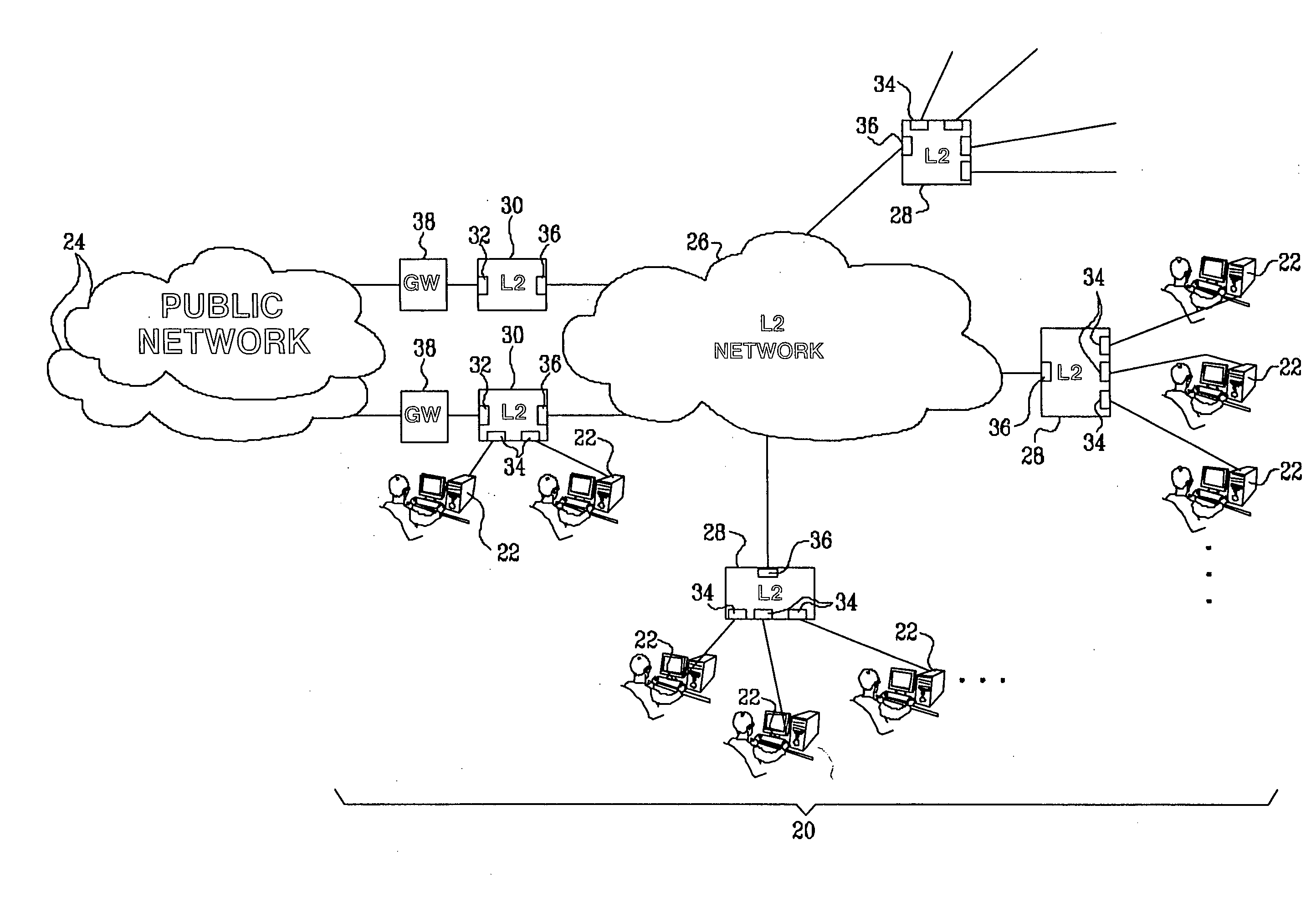
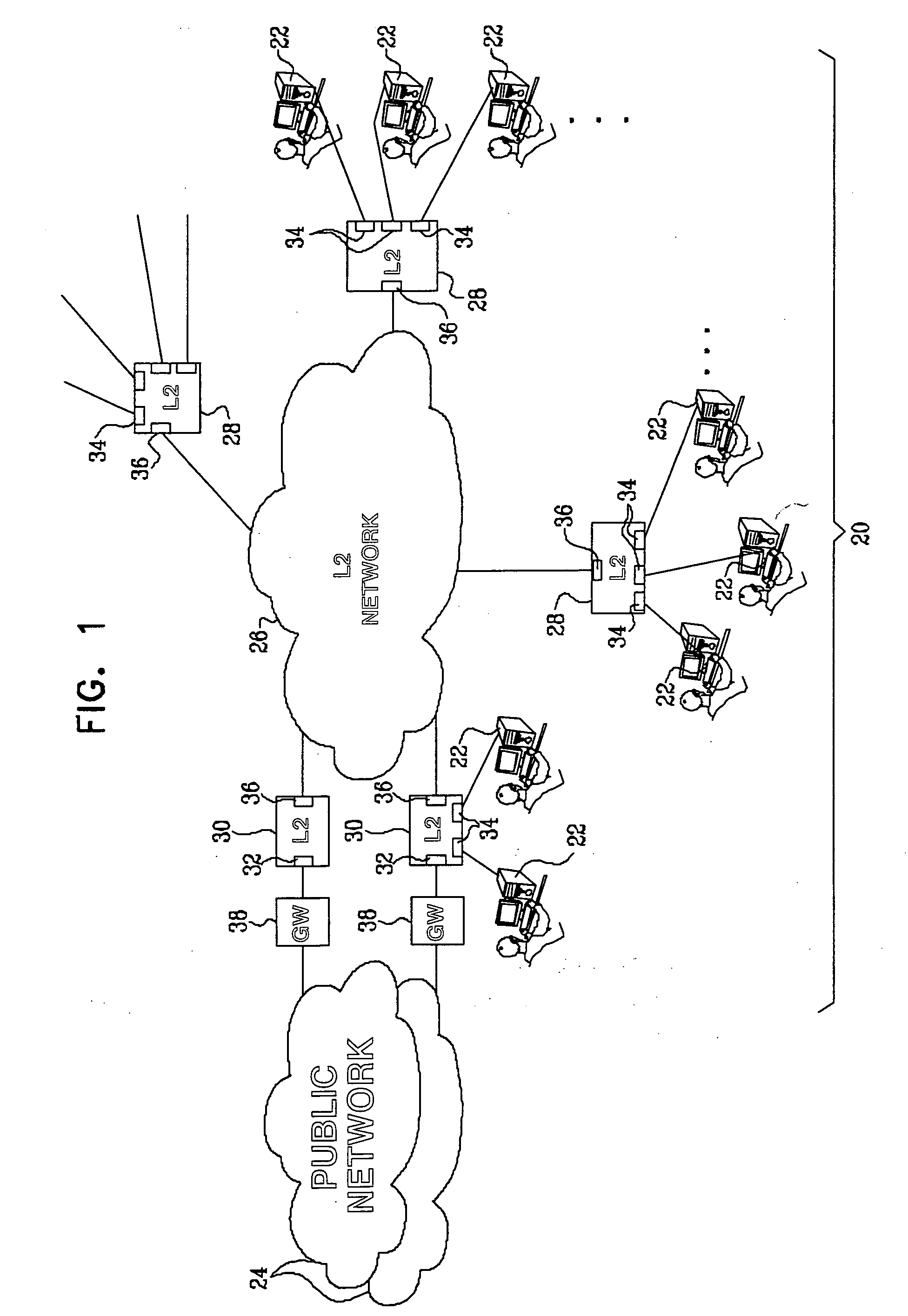
[0032]FIG. 1 is a block diagram that schematically illustrates an access network 20, in accordance with an embodiment of the present invention. Network 20 may be operated, for example, by an ISP in order to permit customer premises equipment (CPE), such as computers 22, to access one or more public networks 24, such as the Internet, via a Layer-2 bridged network 26. Network 20 is configured for P2MP operation between aggregation nodes 30 and computers 22, as is described in detail hereinbelow. This arrangement permits computers 22 to communicate with servers and other client computers via networks 24, as well as to receive network services, such as video over IP multicast. Typically, aggregation nodes 30 connect to networks 24 via suitable gateways 38, as are known in the art. Such gateways may be configured by the ISP to provide routing and security functions, and may also generate service records for billing purposes.

[0033]Alternatively, a similar configuration of network 20 may b...


PUM


Abstract

A method for communication includes coupling a group of switches in a Layer-2 bridged network. The interfaces of the switches are configured so that at least one interface of at least one of the switches is configured as a first interface type, and a plurality of other interfaces are configured as a second interface type. Upon receiving frames through the interfaces of the first and second types for transmission over the network, the received frames are labeled with corresponding first and second type indications. The frames are forwarded through the Layer-2 bridged network using the switches responsively to the type indications. Frames labeled with the second type indication are permitted to be transmitted through the interfaces of the first type and prevented from being transmitted through the interfaces of the second type.

Description

FIELD OF THE INVENTION[0001]The present invention relates generally to communication networks, and specifically to methods and systems for controlling frame transmission through bridged networks.BACKGROUND OF THE INVENTION[0002]Local Area Networks (LANs) connect computing systems together at the Layer-2 level. The term “Layer 2” refers to the second layer in the protocol stack defined by the well-known Open Systems Interface (OSI) model, also known as the logical link, data link, or Media Access Control (MAC) layer. Each computing system connects to a LAN through a MAC device. Multiple LANs can be connected together using MAC bridges, as set forth in the IEEE Standard for Information Technology, Telecommunications and Information Exchange between Systems, Local and Metropolitan Area Networks, Common Specifications, Part 3: Media Access Control (MAC) Bridges, published as ANSI / IEEE Standard 802.1D (2004), which is incorporated herein by reference. (The 802.1D standard, as well as oth...

Claims


Application Information

Patent Timeline
IPC IPC(8): H04L12/56H04J3/16
CPCH04L12/66H04L12/4641H04L63/0227H04L63/162H04L63/0272H04J3/16H04L69/32
Inventor SOLOMON, RONENBRUCKMAN, LEONRAM, RAFIZELIG, DAVIDKATZ, SHACHAR
Owner ORCKIT IP LLC
Why Eureka
Try Eureka