
Fingerprint detection apparatus

Active Publication Date: 2008-02-28
MITSUMI ELECTRIC CO LTD
View PDF1 Cites 92 Cited by
  • Summary
  • Abstract
  • Description
  • Claims
  • Application Information

AI Technical Summary

Benefits of technology

[0013]In the fingerprint detection apparatus according to an embodiment of the present invention, the system controller may intermittently determine whether the finger is in contact with or in the vicinity of the image obtaining part.

Problems solved by technology

However, such detecting parts exhibit difficulty in operating consistently due to, for example, the condition of a finger (moist finger, dry finger) or climate.
Furthermore, since the resistance change detection type or the capacitance change detection type has an electrode provided to its finger-contact area, static electricity having greater energy than the electrode may be applied to the detection apparatus due to discharge of static electricity created from chemical fiber clothing of the user, thereby damaging the electronic circuits inside the detection apparatus.
In a case of using the optical type fingerprint detection apparatus having an optical detecting part mounted outside of the detection apparatus, the detecting part may be adversely affected by factors such as surrounding brightness or disturbance by sunlight.
Furthermore, such an optical type fingerprint detection apparatus is difficult to use for a battery-operated apparatus such as a mobile phone since its light source is required to be lit up when performing fingerprint detection.
This leads to increase of manufacturing cost of the apparatus.

Method used


Image

  • Fingerprint detection apparatus
  • Fingerprint detection apparatus
  • Fingerprint detection apparatus

Examples


Embodiment Construction

[0025]In the following, embodiments of the present invention will be described with reference to the accompanying drawings.

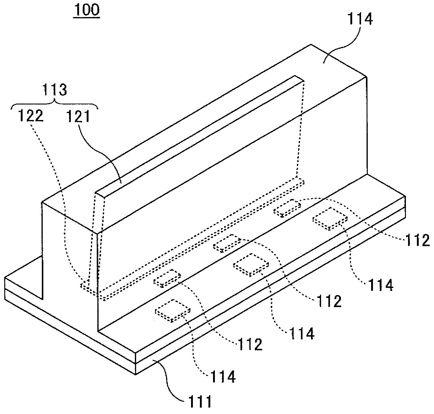
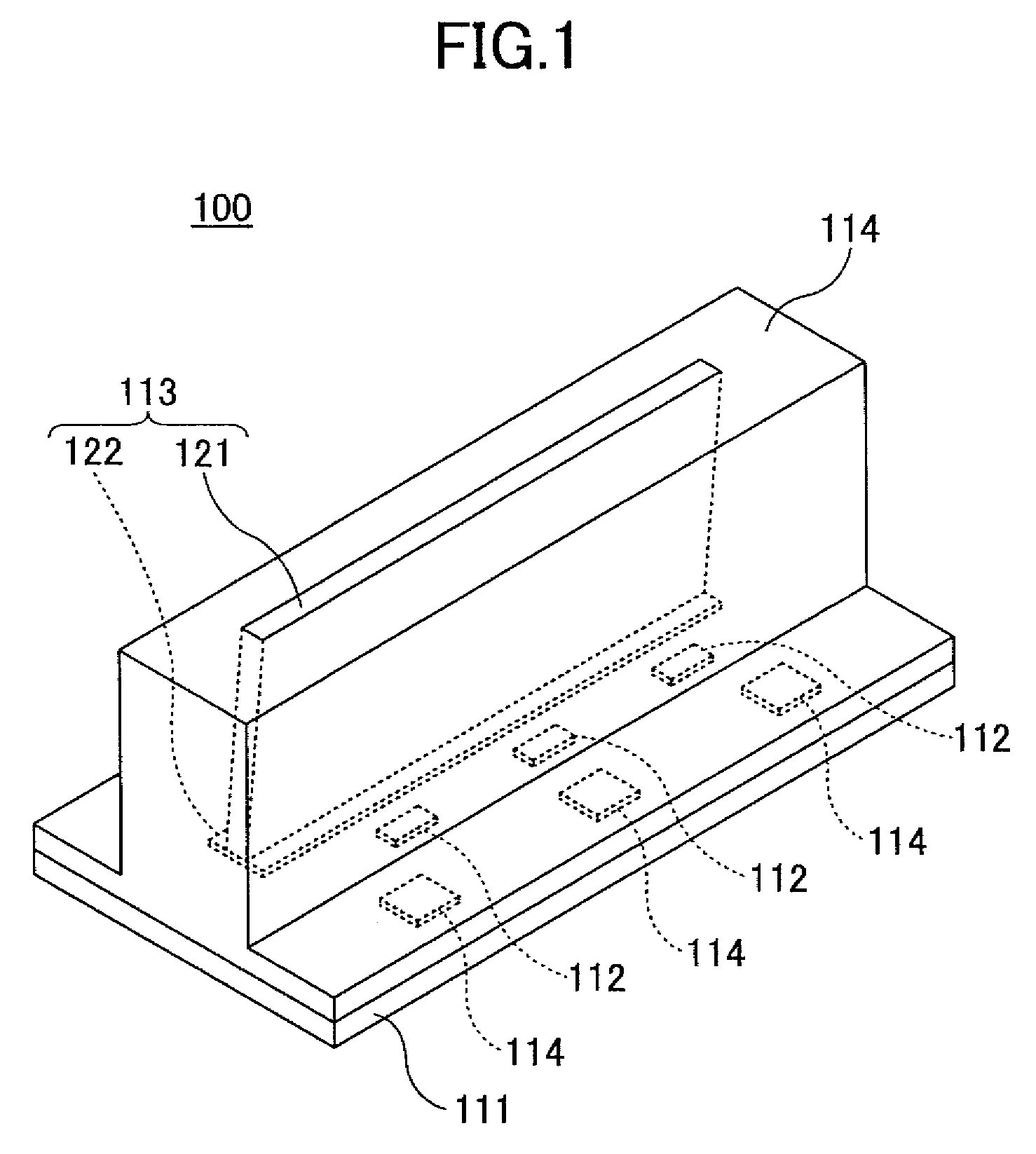
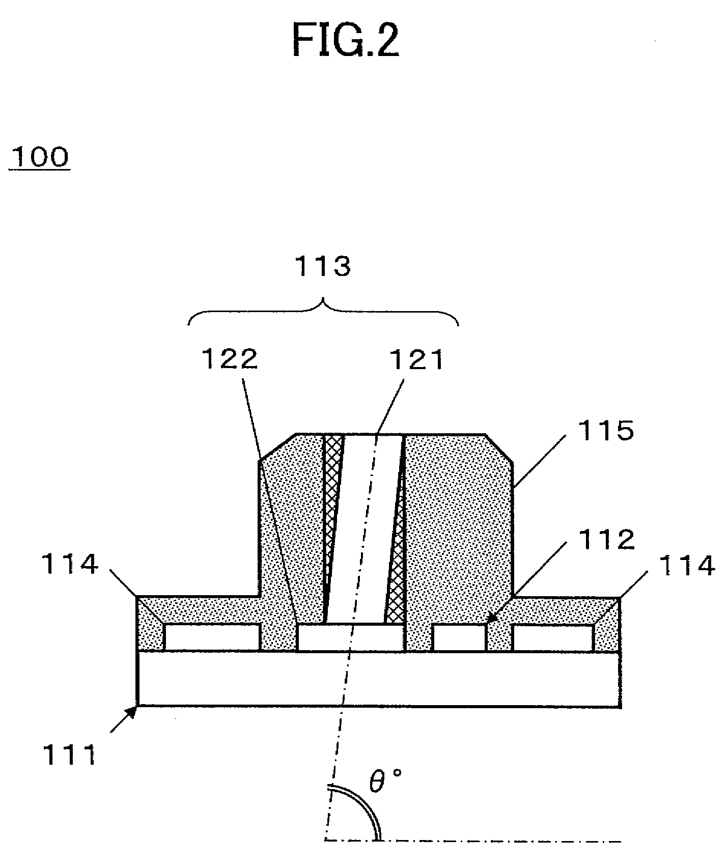
[0026]FIG. 1 is a perspective view showing a fingerprint detection apparatus 100 according to an embodiment of the present invention. FIG. 2 is a cross-sectional view of the fingerprint detection apparatus 100 according to an embodiment of the present invention. FIG. 3 is a schematic diagram for describing the operation of the fingerprint detection apparatus 100 according to an embodiment of the present invention.

[0027]The fingerprint detection apparatus 100 has a circuit board 111 on which one or more light emitting diodes 112, an image obtaining part 113, and various electronic devices 114 are mounted and sealed with a sealing resin 115. The fingerprint detection apparatus 100 uses the light emitting diodes 112 (which are lit mainly for detecting a fingerprint of a finger 101) and the image obtaining part 113 to conducting a finger detection operation (hereina...


PUM


Abstract

A fingerprint detection apparatus for obtaining an image of a fingerprint of a finger by using a light source for emitting a light to the finger and an image obtaining part for outputting electric signals in correspondence with received light is disclosed. The fingerprint detection apparatus includes a system controller for determining whether the finger is in contact with or in the vicinity of the image obtaining part by comparing a threshold with a difference between a value of the electric signal when the light source is lit and a value of the electric signal when the light source is not lit.

Description

BACKGROUND OF THE INVENTION[0001]1. Field of the Invention[0002]The present invention generally relates to a fingerprint detection apparatus, and more particularly to a fingerprint detection apparatus including a light source for irradiating light to a finger and an image detecting part for detecting an image of a fingerprint for detecting a fingerprint based on a detection signal output from the image detecting part.[0003]2. Description of the Related Art[0004]Among various typical fingerprint detection apparatuses, there is, for example, one fingerprint detection apparatus that obtains images of fingerprints by activating a fingerprint detection apparatus using software that controls a system for reducing power consumption, and another fingerprint detection apparatus that obtains images of fingerprints by activating software upon detecting a finger contacting the fingerprint detection apparatus. From the aspect of operability and low power consumption, the latter may be chosen mor...

Claims


Application Information

Patent Timeline
IPC IPC(8): G06K9/00
CPCG06K9/00006G06V40/12
Inventor ISERI, YOICHITAHARA, YOSHINORINAGASHITA, KENICHIROU
Owner MITSUMI ELECTRIC CO LTD
Learn More