Impeller Structure and the Centrifugal Fan Device Using the Same

a centrifugal fan and impeller technology, applied in the direction of machines/engines, stators, liquid fuel engines, etc., can solve the problems of noise, separation and unevenness, high mixing loss at the outlet, etc., and achieve the effect of reducing the thickness of the boundary layer

Inactive Publication Date: 2008-02-28
IND TECH RES INST
View PDF19 Cites 18 Cited by
  • Summary
  • Abstract
  • Description
  • Claims
  • Application Information

AI Technical Summary

Benefits of technology

[0006]It is the primary object of the present invention to provide an impeller structure for a centrifugal fan device, in which each blade structure is comprised of two blades, radially overlapping with each other for forming a gap passage functioning as a nozzle, such that, as a fluidic is flowing through and shooting out of the gap passage, not only the growth of boundary layer can be interrupted, but also the thickness of the boundary layer is reduced.
[0007]It is another object of the present invention to provide an impeller structure for a centrifugal fan device, in which each blade structure is comprised of two blades, radially overlapping with each other for forming a gap passage functioning as a nozzle, such that, as a fluidic is flowing through and shooting out of the gap passage, the separation point is delayed or even prevented for reducing energy loss caused by the separation and flow mixing.
[0008]Yet, another object of the present invention is to provide an impeller structure for a centrifugal fan device, in which each blade structure is comprised of two blades, radially overlapping with each other for forming a gap passage functioning as a nozzle, by which the noise of the impeller structure can be reduced.

Problems solved by technology

Therefore, not only the energy lost in the impeller is increased, but also the wake generated at the outlet area of the impeller is increased that causes high mixing loss at the outlet thereof.
In addition, noises will occur along with the separation and unevenness of flow field.
However, the abovementioned offset centrifugal impeller is not only complicated in structure that it is difficult to process, but also it is difficult to design and analyze.

Method used


Image

  • Impeller Structure and the Centrifugal Fan Device Using the Same
  • Impeller Structure and the Centrifugal Fan Device Using the Same
  • Impeller Structure and the Centrifugal Fan Device Using the Same

Examples


Embodiment Construction

[0021]For your esteemed members of reviewing committee to further understand and recognize the fulfilled functions and structural characteristics of the invention, several preferable embodiments cooperating with detailed description are presented as the follows.

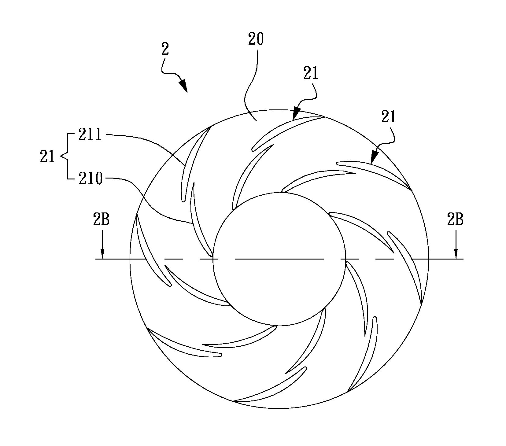
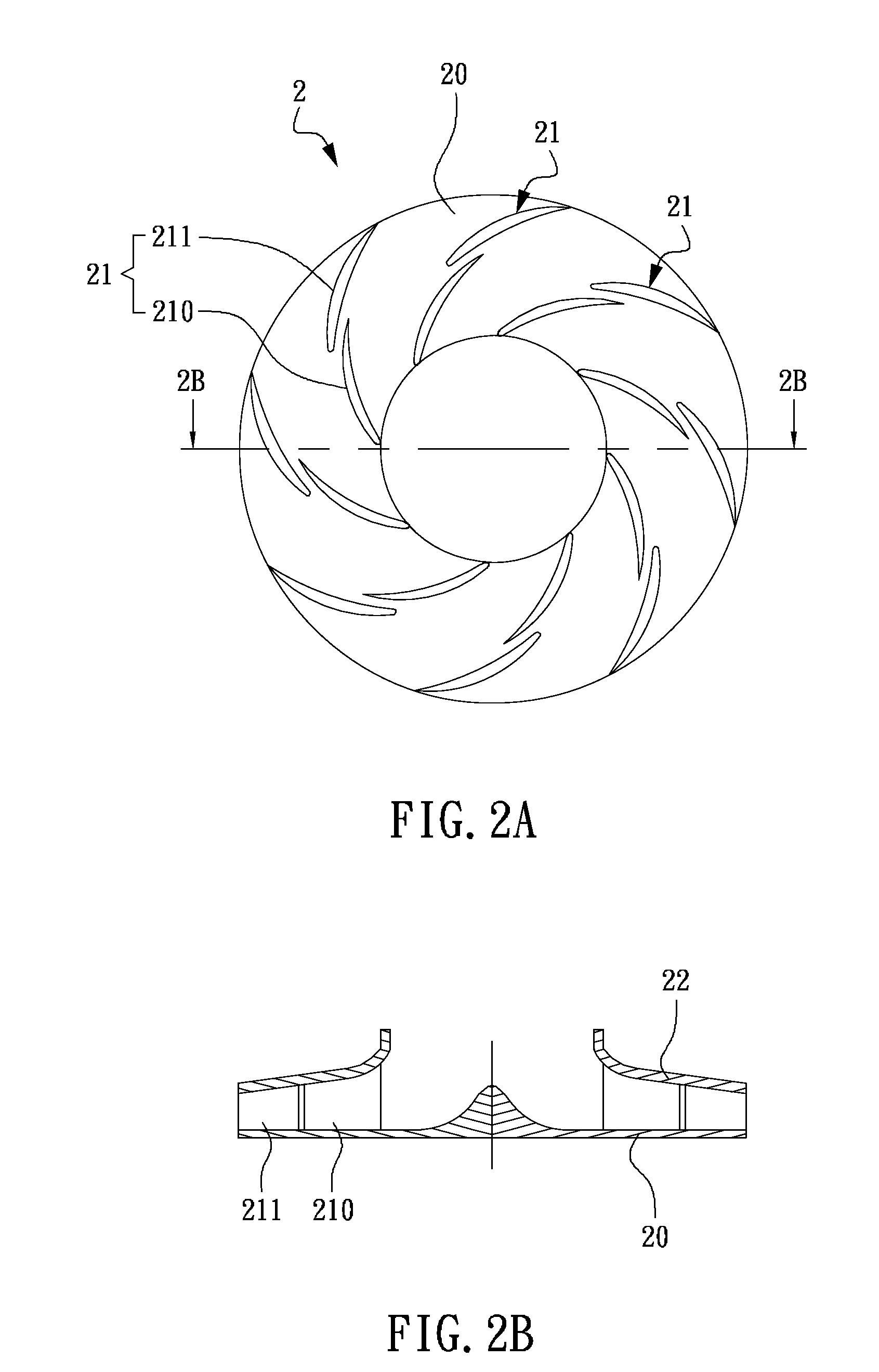
[0022]Please refer to FIG. 2A and FIG. 2B, which are top view and a cross sectional view of an impeller structure according to a preferred embodiment of the invention. The impeller structure 2 is comprised of: a disc 20; and a plurality of blade structures 21, each being arranged on the disc 20 and connected to each other by a front cap 22; wherein, each blade structure 21 further comprises: a first blade 210; and a second blade 211, arranged at a circumferential length away from a side of the first blade 210 while radially overlapping with the radial of the first blade 210 by a overlap area. In this preferred embodiment, the plural blade structures are arranged on the disc 20 in an annular manner.

[0023]Please refer to FIG. 3...


PUM


Abstract

An impeller structure for a centrifugal fan device is disclosed, in which the impeller structure is primarily comprised of: a disc; and a plurality of blade structures, each being arranged on the disc; wherein, each blade structure further comprises: a first blade; and a second blade, arranged at a circumferential length away from a side of the first blade while radially overlapping with the radial of the first blade by a specific overlap area for forming a gap passage functioning as a nozzle. As a fluidic is flowing through and shooting out of the gap passage, not only the growth of the boundary layers on the suction surfaces of front blades are interrupted, but also as the fluidic with high kinetic energy is mixing with the low-kinetic fluidic flowing on the suction surfaces of rear blades, the thickness of the boundary layer is reduced while the separation point is delayed and thus separation can be prevented.

Description

FIELD OF THE INVENTION[0001]The present invention relates to an impeller structure, and more particularly, to an impeller structure for a centrifugal fan device, in which each blade structure of the impeller structure is primarily comprised of: a first blade; and a second blade, arranged at a circumferential length away from a side of the first blade while radially overlapping with the radial of the first blade by a specific overlap area for forming a gap passage functioning as a nozzle.BACKGROUND OF THE INVENTION[0002]As centrifugal impeller is the heart of a centrifugal fan, it plays an important role in factors affecting the performance and noise of the centrifugal fan. Centrifugal fans are subclassified in the literature according to their impeller and blade designs. The impeller and blade designs employed in the commercially available centrifugal fans are the backward curved, radial, and forward curved. Of these, the backward curved type has been recognized as being most effici...

Claims


Application Information

Patent Timeline
Patent Type & Authority Applications(United States)
IPC IPC(8): F03B3/16
CPCF04D29/30F04D29/281
Inventor CHEN, JIING-FUWU, TUNG-CHUANLO, CHAN-HSINGCHIANG, CHUNG-PINGCHUNG, YU-LIANGSUN, YANN-SHUOH
Owner IND TECH RES INST
Why Eureka
Try Eureka