Diaphragm Pump and Manufacturing Device of Electronic Component

a technology of electronic components and manufacturing devices, which is applied in the direction of pump components, positive displacement liquid engines, liquid fuel engine components, etc., can solve the problems of reducing the manufacturing reducing the production efficiency of electronic components, and reducing defective products.

Inactive Publication Date: 2008-02-28
NOIBERUKU
View PDF7 Cites 6 Cited by
  • Summary
  • Abstract
  • Description
  • Claims
  • Application Information

AI Technical Summary

Benefits of technology

[0008]An object of the present invention is to provide a diaphragm pump capable of operating with minimal pulsation and g liquid to flow back without necessity of the use of a check valve, size and weight of which can be easily reduced, and also to provide a manufacturing device of electronic component using the diaphragm.
[0010]With the above-described arrangement according to the present invention, each of the valve chambers can be opened and closed, and the volume of the metering chamber can be increased and decreased by driving each of the pressing members corresponding to each of the valve chambers and the metering chamber arranged along each of the liquid flow paths to reciprocate at predetermined timings. Therefore, liquid is prevented from flowing backward without using a check valve when each of the pressing members is moved at predetermined timings while the liquid is being transferred. Thus, since no check valve is provided, each of the pressing members can be driven to move reversely so as to allow liquid to flow backward.

Problems solved by technology

However, such diaphragm pumps normally generate pulsation because liquid is taken in and discharged by reciprocating the diaphragm.
In other words, they are accompanied by a problem that they cannot allow liquid to flow back.
In the pump disclosed in Reference 2, since the diaphragm is deformed by a liquid, it is difficult to speed up a drive operation, and since chambers of plural systems are provided in parallel, it is difficult to reduce size and weight.

Method used


Image

  • Diaphragm Pump and Manufacturing Device of Electronic Component
  • Diaphragm Pump and Manufacturing Device of Electronic Component
  • Diaphragm Pump and Manufacturing Device of Electronic Component

Examples


first embodiment

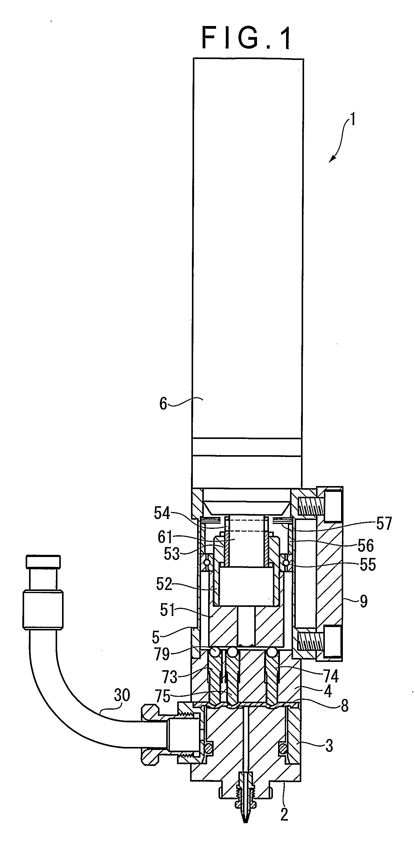
[0101]FIG. 1 is a schematic view of the first embodiment of a diaphragm pump 1 according to the present invention.

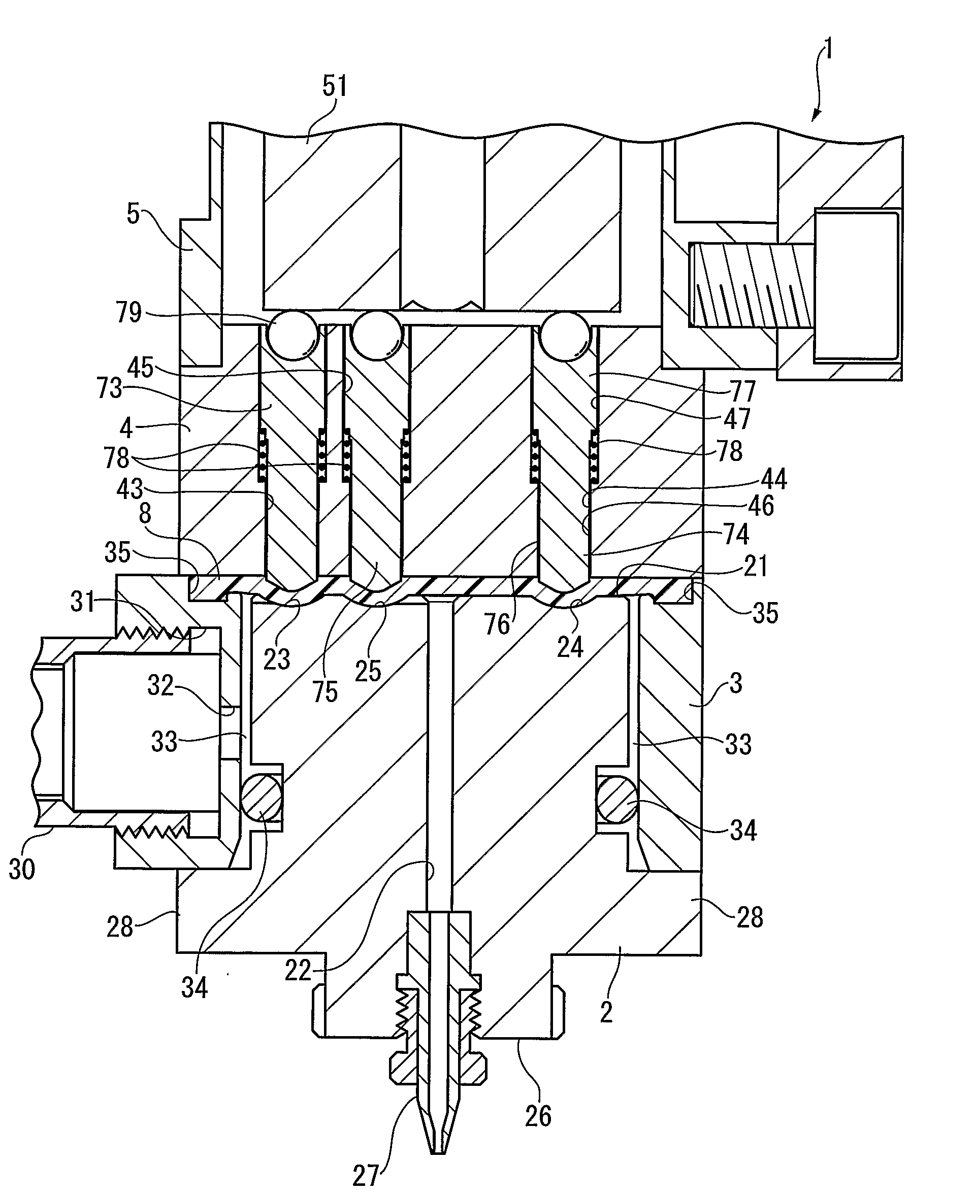
[0102]The diaphragm pump 1 has a base block 2, a holder ring block 3, a guide block 4, a fitting block 5 and a drive unit 6.

[0103]Each of the brocks 2 through 5 is provided with through holes (not shown) at the four comers thereof. Each of the blocks 2 through 5 is assembled by means of a coupling bolt penetrating through the base block 2 and the holder ring block 3 to be screwed into the guide block 4, a coupling bolt screwed into the guide block 4 via the fitting block 5, a coupling bolt screwed into the drive unit 6 via the fitting block 5 and so on. Positioning pins are also used to align the blocks.

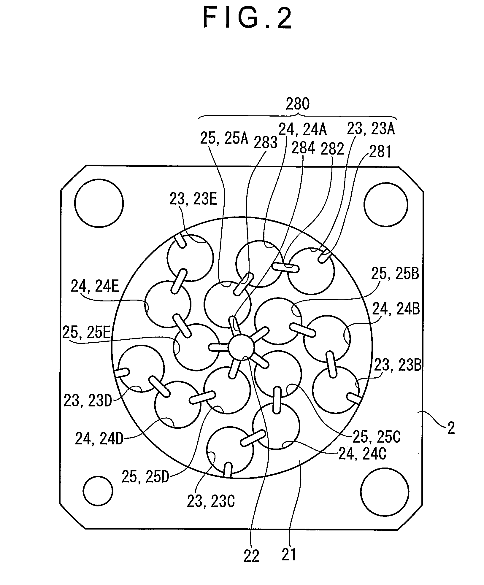
[0104]As shown in FIGS. 2 and 3, the base block 2 has a recess forming surface 21 that is a diaphragm-contacting surface opposed to the guide block 4. The recess forming surface 21 is formed by a planar area defined to show a substantially circular boundary. A port 22 is ...

second embodiment

[0243]Next, the second embodiment of the present invention will be described by referring to FIGS. 13 and 14A through 14C.

[0244]A diaphragm pump 1A of the second embodiment differs from the diaphragm pump 1 of the first embodiment in arrangements of a base block 2A and a diaphragm 8A. More specifically, of the base block 2A of the second embodiment, a diaphragm-contacting surface 21A that closely contacts to the diaphragm 8A is planar without grooves and recesses formed thereon, which is different from the recess forming surface 21 of the first embodiment where the recesses 23 through 25 and the communication grooves 281 through 284 are formed.

[0245]The diaphragm 8A shows a substantially disk-like profile, which include a flow-path-block-contacting surface 81 that faces the base block 2A and a pressing-rod-abutting surface 82 that faces the pressing rods 73 through 75.

[0246]The flow-path-block-contacting surface 81 is not planar unlike the diaphragm 8 of the first embodiment, and th...

third embodiment

[0255]Next, a third embodiment of the present invention will be described with reference to FIGS. 15 through 24.

[0256]A diaphragm pump 1B of the third embodiment differs from the diaphragm pump 1 of the first embodiment in arrangements of a flow path block 130 and a cam 150. The flow path block 130 includes a metal base 131 and an abutment 132 made of synthetic resin such as polypropylene.

[0257]The abutment 132 includes a recess forming surface 132A as a diaphragm-contacting surface for the diaphragm 8 to be closely attached thereto. Formed on the recess forming surface 132A are the recesses 23 through 25 and communication grooves 281 through 284, as with the recess forming surface 21 of the first embodiment shown in FIG. 2.

[0258]A plurality of protrusions 132B are formed on the abutment 132, the protrusions 132B inserted into a fitting hole 131A of the base 131 for positioning.

[0259]A through hole being the port 22 is formed at a central axis portion of the abutment 132. A nozzle c...


PUM


Abstract

A diaphragm pump 1 has a base block 2, a diaphragm 8 and a drive unit for driving the diaphragm to reciprocate. The base block 2 has three or more liquid flow paths, each having three recesses 23 through 25 or more recesses. The diaphragm 8 and the respective recesses 23 through 25 define a plurality of valve chambers and the metering chamber The drive unit includes: pressing rods 73 through 75 arranged corresponding to the respective recesses with the diaphragm interposed therebetween; and a pressing member drive controller adapted to execute a liquid discharging operation and a liquid sucking operation at a predetermined timing defined for each of the pressing rods, in which in the liquid discharging operation, each of the pressing rods is moved toward the respective recesses so as to gradually decease the volume of the respective valve chambers and the metering chamber and eventually hermetically seal the metering chamber; while in the liquid discharging operation, each of the pressing rods is moved away from the respective recesses so as to gradually decease the volume of the respective valve chambers and the metering chamber.

Description

TECHNICAL FIELD[0001]The present invention relates to a diaphragm pump for transferring a predetermined volume of liquid and a manufacturing device of electronic component. The diaphragm pump according to the present invention can find applications in the field of continuously transferring (discharging) liquid, which may be selected from acidic or alkaline medicinal liquids, soldering pastes, solvents such as alcohol and adhesives with minimal pulsation. The diaphragm pump can and further find applications in manufacturing devices of electronic components such as a die bonder, in which a semiconductor chip is fixed to the substrate by the adhesives discharged from a diaphragm pump, or a manufacturing device for manufacturing light-emitting diode (LED), in which the LED chip is sealed by the resin discharged from a diaphragm pump, or the like.BACKGROUND ART[0002]Diaphragm pumps using a diaphragm made of synthetic resin thin film are being used in various industrial fields including t...

Claims


Application Information

Patent Timeline
Patent Type & Authority Applications(United States)
IPC IPC(8): F04B39/10F04B43/02F04B43/08
CPCF04B43/025F04B43/021
Inventor OGAWA, KENJI
Owner NOIBERUKU
Why Eureka
Try Eureka