A high-speed permanent magnet brushless DC motor control method based on variable conduction period

A permanent magnet brushless DC, motor control technology, applied in motor control, current controller, control system, etc., can solve the increase of motor electromagnetic torque ripple, loss and inverter stress increase, current RMS and peak value Increase and other problems to achieve the effect of reducing rotor eddy current loss, minimizing pulsation, and improving current waveform

Active Publication Date: 2018-12-18
ZHEJIANG UNIV
View PDF6 Cites 8 Cited by
  • Summary
  • Abstract
  • Description
  • Claims
  • Application Information

AI Technical Summary

Problems solved by technology

However, during ultra-high-speed operation, the inductance of the motor winding has a great influence. In the ideal commutation mode, the motor current will lag behind the back EMF, resulting in a decrease in the equivalent power factor of the motor, and an increase in the effective value and peak value of the current. The loss and the stress of the inverter increase. Since the current lag angle changes with the change of the motor speed and load, it cannot be solved by fixed advance commutation. With the increase of the commutation lead angle, the electromagnetic torque ripple of the motor will will increase

Method used


Image

  • A high-speed permanent magnet brushless DC motor control method based on variable conduction period
  • A high-speed permanent magnet brushless DC motor control method based on variable conduction period
  • A high-speed permanent magnet brushless DC motor control method based on variable conduction period

Examples


Embodiment Construction

[0043] In order to describe the present invention more specifically, the technical solutions of the present invention will be described in detail below in conjunction with the accompanying drawings and specific embodiments.

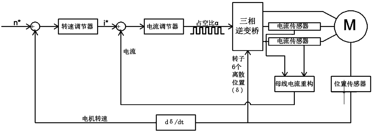
[0044] figure 1 It is a block diagram of a traditional permanent magnet brushless DC motor speed and current double closed-loop PWM control system. The control strategy adopts a three-phase six-state 120° conduction mode, and each state conducts two power switch tubes. The conduction period of each power tube For an electrical angle of 120°, the Hall position sensor of the motor provides the position information required for state switching. According to the principles of electromechanics, in order to realize the speed regulation of the brushless DC motor, the voltage applied to both ends of the motor winding must be changed. The traditional control method is to generate a PWM wave with a fixed chopping cycle and an adjustable duty cycle and the 120° con...


PUM


Abstract

The invention discloses a control method of a high-speed permanent magnet brushless DC motor based on a variable conduction period, The method realizes stepless speed regulation by adjusting the conduction period of control signal, obtains the required conduction period by speed-current double closed-loop control, divides the conduction period into one pulse, two symmetrical pulses or two asymmetrical pulses according to the principle of minimum current ripple, and then applies the conduction period to each power transistor according to three-phase six-state conduction law. As that optimal commutation angle is dynamically adjusted, the high-speed running current waveform of the motor system can be completely symmetrical and the ripple is minimum, the stator current waveform of the high-speed permanent magnet brushless DC motor can be effectively improved, and the eddy current loss of the rotor can be reduced.

Description

technical field [0001] The invention belongs to the technical field of motor control, and in particular relates to a high-speed permanent magnet brushless DC motor control method based on a variable conduction period. Background technique [0002] The permanent magnet brushless DC motor is mainly composed of three parts: the motor body, the rotor position sensor and the power inverter circuit. It is a typical mechatronic motor. The structure of the motor body is similar to that of ordinary synchronous motors. The stator generally adopts three-phase windings, and the rotor adopts permanent magnet excitation; the power inverter circuit inverts the DC power supply into AC power according to the conduction sequence output by the rotor position sensor, which is used to power the motor stator. The three-phase winding supplies power in order to interact with the permanent magnetic field of the rotor to generate continuous electromagnetic torque; the power inverter circuit generally...

Claims


Application Information

Patent Timeline
IPC IPC(8): H02P6/10H02P6/17H02P6/28
CPCH02P6/10H02P6/17H02P6/28H02P2205/01H02P2205/07
Inventor 史涔溦邱建琪李启俊
Owner ZHEJIANG UNIV
Why Eureka
Try Eureka