Inductance coil charging and discharging power supply with low harmonic output

A charge-discharge power supply and inductance coil technology, which is applied in transformer/inductor circuits, output power conversion devices, AC power input conversion to AC power output, etc., can solve the problem that single-phase inverter power supply and control methods cannot fully meet the technical requirements Index requirements and other issues to achieve the effect of avoiding electromagnetic interference, good effect, and smooth current waveform

Active Publication Date: 2021-12-10
GUANGDONG FULLDE ELECTRONICS
View PDF1 Cites 2 Cited by
  • Summary
  • Abstract
  • Description
  • Claims
  • Application Information

AI Technical Summary

Problems solved by technology

For such a special current waveform, the conventional single-phase inverter power supply and control method cannot fully meet the technical index requirements. Therefore, the present invention proposes a power supply and a realization method that can achieve similar current and voltage strict technical index requirements

Method used


Image

  • Inductance coil charging and discharging power supply with low harmonic output
  • Inductance coil charging and discharging power supply with low harmonic output
  • Inductance coil charging and discharging power supply with low harmonic output

Examples


Embodiment Construction

[0033] Exemplary embodiments of the present disclosure will be described in more detail below with reference to the accompanying drawings. Although exemplary embodiments of the present disclosure are shown in the drawings, it should be understood that the present disclosure may be embodied in various forms and should not be limited by the embodiments set forth herein. Rather, these embodiments are provided for more thorough understanding of the present disclosure and to fully convey the scope of the present disclosure to those skilled in the art.

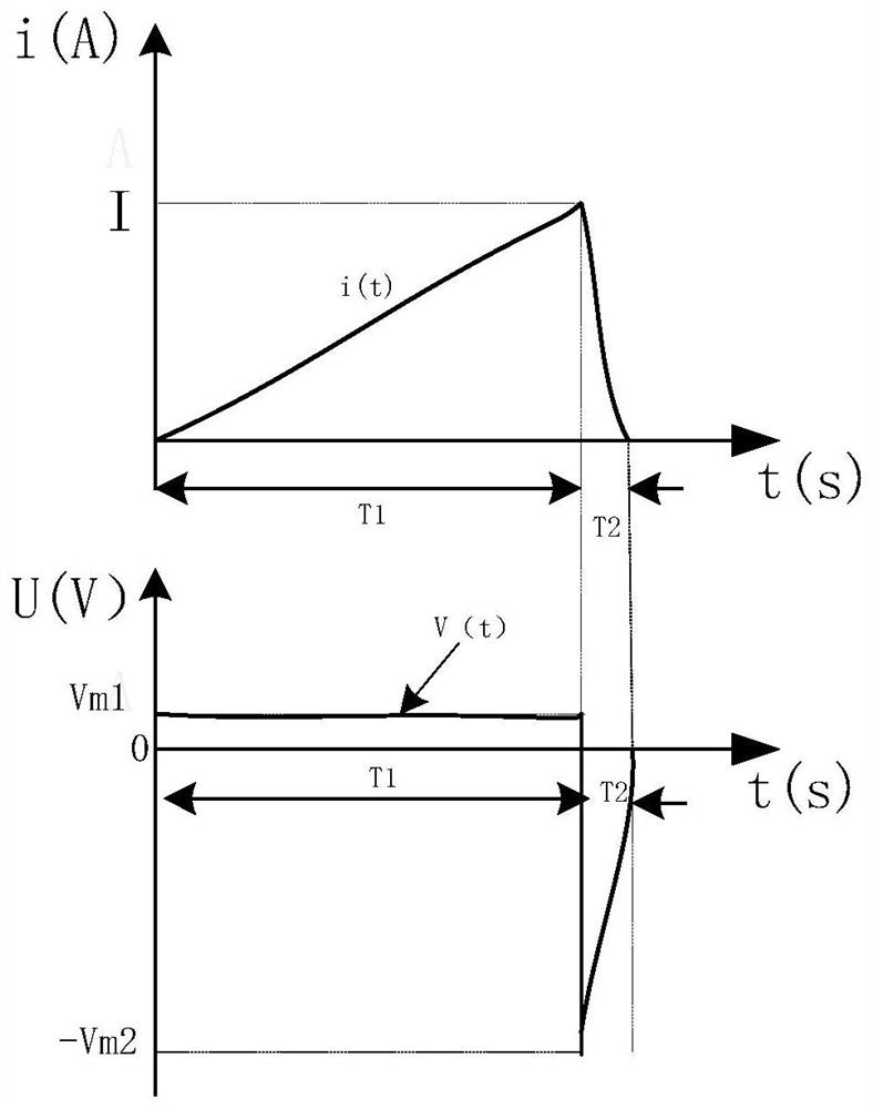
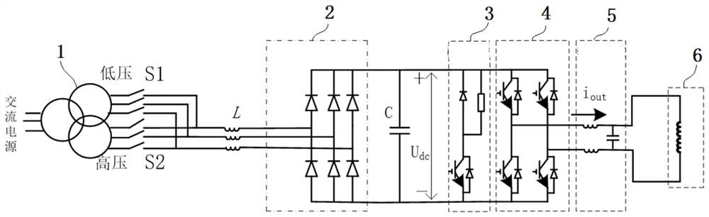
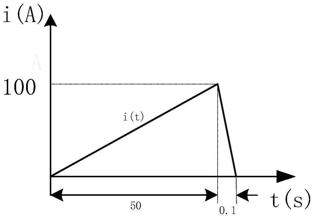
[0034] In order to achieve something like figure 1 The current and voltage waveforms of the inductance coil shown, the power supply system proposed by the present invention adopts figure 2 As shown in the electrical topology scheme of the main circuit, the main circuit of the whole system is mainly composed of transformer 1, high and low voltage switch S1 and S2, current limiting inductor L, diode rectifier circuit 2, overvoltage ...


PUM


Abstract

The invention relates to an inductance coil charging and discharging power supply with low harmonic output. The inductance coil comprises: a diode rectifying circuit, an H-bridge inverter and an inductance coil which are electrically connected in sequence, wherein a current-limiting inductor is connected in series on the input side line of the diode rectifying circuit, and a support capacitor C is bridged between a positive bus and a negative bus on the output side; a low-voltage output circuit connected to the input end of the diode rectifying circuit through a switch S1, and a high-voltage output circuit connected to the input end of the diode rectifying circuit through a switch S2, wherein the voltage of the low-voltage output circuit is small enough so as to make the amplitude of high-frequency harmonic current of the inductance coil be smaller than 1A when the current slowly rises, and the voltage of the high-voltage output line is large enough so as to make the direct-current voltage of the direct-current side of the H-bridge inverter be larger than the electromotive force generated by the inductance coil when the current drops sharply; and a current sensor used for collecting the current of the output side of the H-bridge inverter, and a controller used for receiving the electrical parameters of the current sensor and controlling the turn-off of the H-bridge inverter.

Description

technical field [0001] The invention relates to the fields of nuclear fusion plasma motion control or electromagnetic energy storage and release, and in particular relates to an inductance coil charging and discharging power supply with low harmonic output. Background technique [0002] In the specific research field of using a magnetic field to control the position of charged particles, some special-purpose inductance coils are required, and the current or voltage process waveform technology of these inductance coils requires special requirements. figure 1 A schematic diagram of typical current and voltage waveforms for an inductor coil is shown. In a longer time T1 (such as 50 seconds), the DC current in the inductance coil needs to be gradually increased from 0 to a certain maximum value I (such as 250A) under the control of an external power supply, and in the subsequent T2 time In the period, its current changes from I to 0 again. During T1, the voltage of the inducta...

Claims


Application Information

Patent Timeline
Patent Type & Authority Applications(China)
IPC IPC(8): H02M5/458H02M7/5387H02M1/12H02M1/32H02M1/44H01F27/42
CPCH02M5/458H02M7/53871H02M1/12H02M1/32
Inventor 刘湘盛建科廖晓斌盛亮科甘义成
Owner GUANGDONG FULLDE ELECTRONICS
Why Eureka
Try Eureka