Method for transmitting fast scheduling request messages in scheduled packet data systems

a packet data and request message technology, applied in the field of scheduled packet data systems, can solve the problems of inacceptable latency periods of 50-60 ms, and achieve the effect of reducing latency

Inactive Publication Date: 2008-02-28
LUCENT TECH INC
View PDF8 Cites 127 Cited by
  • Summary
  • Abstract
  • Description
  • Claims
  • Application Information

AI Technical Summary

Benefits of technology

[0016]An embodiment of the present invention is a method of allocating resources in a packet data system to a User Equipment (UE) with an active data session, such as a Voice over Internet Protocol (VoIP) call, using dedicated resources to transmit scheduling requests, thereby reducing latency which may occur as a result of collisions associated with transmitting scheduling requests over a random access channel. In one embodiment, the method comprises the step of transmitting over dedicated resources a scheduling request, and receiving a scheduling grant in response thereto. The scheduling request indicates that a transmitter in a data session has a data packet to transmit. The scheduling grant indicates resources allocated for transmitting the data packet.

Problems solved by technology

The latency period is due, in large part, to delays associated with the UE waiting for the synchronized RACH to become available, collisions occurring on the synchronized RACH and / or insufficient initial transmit power for the SRM.
Such delays may result in latency period being upwards of 50-60 ms.
For time sensitive data applications, such as VoIP calls, latency periods upward of 50-60 ms are unacceptable.

Method used


Image

  • Method for transmitting fast scheduling request messages in scheduled packet data systems
  • Method for transmitting fast scheduling request messages in scheduled packet data systems
  • Method for transmitting fast scheduling request messages in scheduled packet data systems

Examples


first embodiment

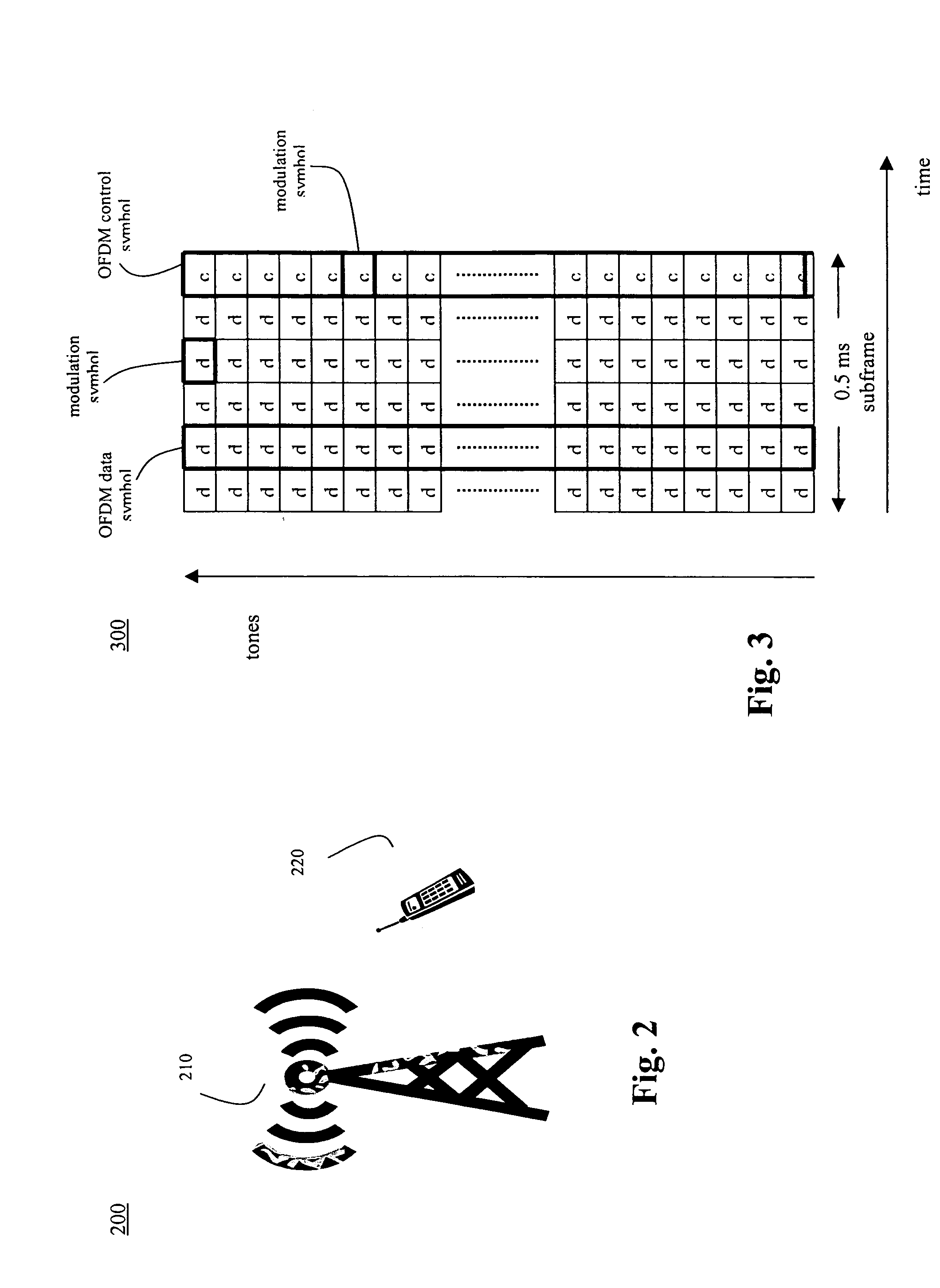
[0026]In a first embodiment, dedicated resources are allocated solely for transmission of the SRM or derivative thereof. For example, resources corresponding to a subframe, or part thereof, may be reserved every X ms, e.g., 10 ms, for use by UEs with active data sessions, where X is greater then the time interval associated with the subframe, e.g., 0.5 ms. These reserved resources are partitioned in terms of frequency and / or time into dedicated resources which could then be allocated to specific UEs for transmissions of SRMs or derivative thereof.

second embodiment

[0027]In a second embodiment, the SRMs or derivative thereof can be transmitted over dedicated resources used to transmit other types of information. For example, in UMTS, dedicated resources may be allocated for a Reverse Channel Quality Indicator CHannel (R-CQICH) over which a Channel Quality Indicator (CQI) is transmitted. The SRM or derivative thereof may be combined with the CQI and transmitted over the R-CQICH. The SRM or derivative thereof may be combined with the CQI by adding, e.g., appending or prepending, the SRM or derivative thereof to the CQI. Or the SRM or derivative thereof may be combined with the CQI by substituting a part of the CQI with the SRM. After the SRM or derivative thereof has been combined with the CQI, for example, the combination may be encoded or otherwise processed prior to being transmitted over the dedicated resources.

[0028]FIG. 4 depicts a chart 400 illustrating a method of allocating dedicated resources to a UE with an active VoIP call (or some o...


PUM


Abstract

Disclosed is a method of allocating resources in a packet data system to a User Equipment (UE) with an active data session, such as a Voice over Internet Protocol (VoIP) call, using dedicated resources to transmit scheduling requests, thereby reducing latency which may occur as a result of collisions associated with transmitting scheduling requests over a random access channel. The method comprises the step of transmitting over dedicated resources a scheduling request, and receiving a scheduling grant in response thereto. The scheduling request indicates that a transmitter in a data session has a data packet to transmit. The scheduling grant indicates resources allocated for transmitting the data packet.

Description

FIELD OF THE INVENTION[0001]The present invention relates generally to wireless communication systems and, in particular, to scheduled packet data system.BACKGROUND OF THE RELATED ART[0002]To increase system capacity, Universal Mobile Telecommunication System (UMTS) based wireless communication systems will evolve to a packet data system. All services, including voice services, will be supported by the packet data system. The packet data system will use an Orthogonal Frequency Division Multiple Access (OFDMA) air interface for transmitting data packets between Node Bs and User Equipments (UE). The OFDMA air interface comprises a set of orthogonal sub-carrier frequencies, i.e., resources, which are partitioned in terms of frequency and / or time into reverse link and forward link resources.[0003]In the packet data system, the reverse link resources may be dedicated resources or shared resources. For purposes of this application, the term “dedicated resources” should be construed to mea...

Claims


Application Information

Patent Timeline
Patent Type & Authority Applications(United States)
IPC IPC(8): H04Q7/20H04W74/08
CPCH04W74/0866H04W74/002
Inventor RAO, ANIL M.
Owner LUCENT TECH INC
Why Eureka
Try Eureka