
Level indicator for snow plow

a level indicator and snow plow technology, applied in the field of snow plows, can solve the problems of difficulty for operators to see whether the reference wand and the guage coincide, and operators either ignore the guage or take frequent breaks

Inactive Publication Date: 2008-03-06
ADEPCO TECH
View PDF24 Cites 15 Cited by
  • Summary
  • Abstract
  • Description
  • Claims
  • Application Information

AI Technical Summary

Benefits of technology

"The invention is a level indicator for a snow plow assembly that includes a reference wand and a pendulum guage. The pendulum guage is pivotally mounted between the reference wand and has a counterweight at one end to dampen its swing. The indicator means at the other end of the pendulum guage indicate its position relative to the reference wand. This allows for easy and accurate measurement of the snow plow assembly's level."

Problems solved by technology

It is sometimes difficult for an operator to see whether the reference wand and the guage coincide.
This is further compromised by the guage being in constant motion as the snow plow must by necessity move over uneven terrain with the result that the operator either ignores the guage or takes frequent breaks to wait for the guage to come to an equilibrium rest position.

Method used


Image

  • Level indicator for snow plow
  • Level indicator for snow plow
  • Level indicator for snow plow

Examples


Embodiment Construction

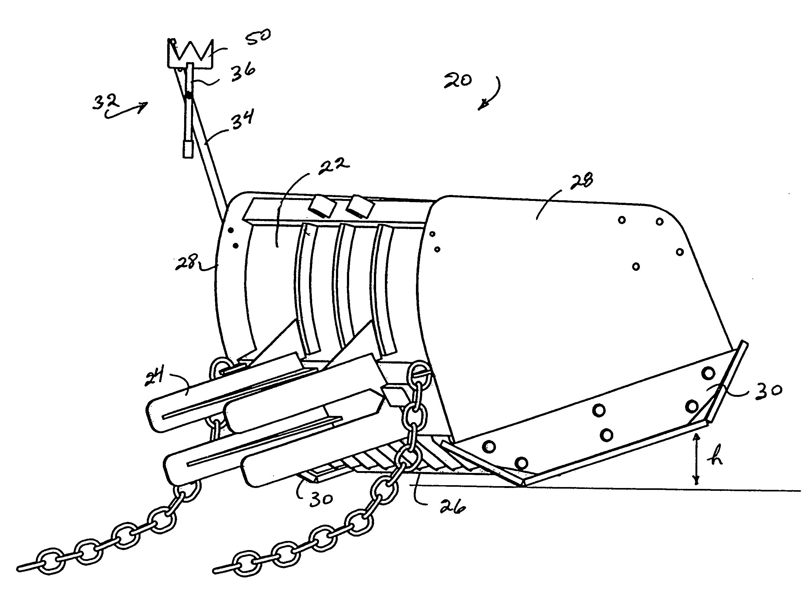
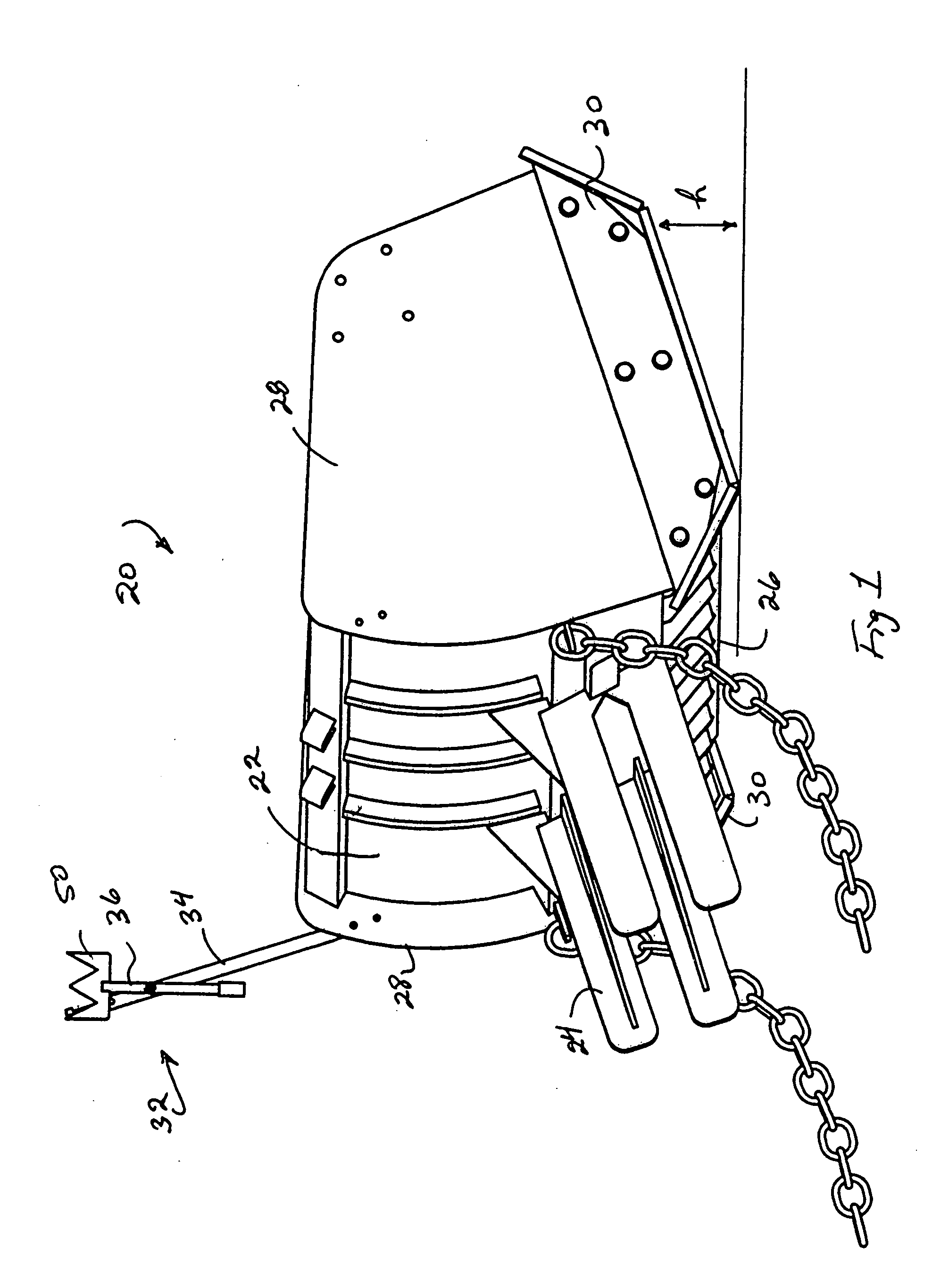
[0013]A snow plow assembly is generally indicated in the drawings by reference numeral 20 and consists of a moldboard 22 which in use is pushed by a driven vehicle (not shown) that is coupled using a receiver 24 extending rearwardly from the rear surface of the moldboard 22. The snow is scraped with a blade 26 that extends along the length of the moldboard 22 at a bottom edge thereof. Any snow pushed by the plow is contained between sides 28 that extend the full height of the moldboard 22 and forwardly. The bottom surface of each of the sides 28 is protected with a shoe 30 that is removably coupled to a side 28 and that can be replaced, as the need arises. During use, the snow plow assembly 20 is not always level and can, for example be tilted upwardly, as shown in FIG. 1 by the separation height “h” indicated at the forward end of the sides 28 which shows the height of the sides 28 above ground. This results in wear at the back of the shoes 30.

[0014]In accordance with this inventio...


PUM


Abstract

A level indicator for a snow plow assembly has a reference wand and a pendulum guage pivoted to the reference wand. The reference wand has a bend at a top end with a reference mark to lie over the pendulum. The pendulum guage has a counterweight to dampen its swing and has an indicator. The indicator aligns with the reference mark in a level position of the snow plow assembly and the swing of the pendulum is limited by interference with the reference wand between extreme positions where the snow plow assembly is tilted.

Description

FIELD OF THE INVENTION[0001]This invention relates to a snow plow and in particular relates to a level indicator to show whether the moldboard in a snow plow is level with the ground as otherwise shoes provided to protect side plates for the moldboard will become worn.BACKGROUND OF THE INVENTION[0002]In a snow plow assembly, the snow plow has a receiver for coupling to a driven vehicle. The receiver extends rearwardly from a moldboard that is forwardly curved for pushing snow that is contained between side plates for the moldboard. The side plates have bottom edges which slide on the ground or other surface being cleared of snow and are protected with so-called shoes which can be replaced, as the case may be, according to wear of the shoes. It is of course preferable to minimize the wear of the shoes as much as possible, and therefore level indicators are provided to operators of the plow so they can adjust the tilt of the moldboard in such a way as to minimize the wear on the shoes...

Claims


Application Information

Patent Timeline
Patent Type & Authority Applications(United States)
IPC IPC(8): B60K37/00
CPCG01C9/12E01H5/066
Inventor PAONESSA, GINO
Owner ADEPCO TECH
Learn More