
Grass Protection Mat and Mat Assembly Having the Same

Active Publication Date: 2008-03-06
SON GYEUL
View PDF37 Cites 11 Cited by
  • Summary
  • Abstract
  • Description
  • Claims
  • Application Information

AI Technical Summary

Benefits of technology

[0021] According to the invention, the grass protection mat is effectively prevented from sinking into the ground after installed on the ground, and provides enhanced protection and growth of grass.
[0022] In addition, the mat assembly including the grass protection mat of the present invention facilitates connection of the mats as well as installation of the mats on the ground where grass is actually grown and protected, thereby improving productivity in installation of the mats while saving the installation costs of the mats.

Problems solved by technology

In the places where grass is grown, such as golf courses, grass ballparks or parks, grass is easily pressed down and damaged in the area which is subject to human or vehicular traffic (e.g. a golf cart).
Repairing the damaged grass requires considerable amount of costs.
In the conventional grass protection mats known to date, simple L-shaped or button-shaped hooks are used to connect the mats, in which the operation is difficult and vertical pushing and fitting is inconvenient for actual connection of the mats.
Particularly, the conventional hooks are detached too easily from the outer frame of the mat when the mats are assembled.
In the meantime, the conventional grass protection mats (refer to FIG. 13) use wires to connect the corners of the mats, and thus the installation of the mats as well as separation of the mats for repair is difficult.
In addition, after the conventional mats are installed on the ground to protect grass, they sink into the ground over time, not effective in protection of the grass.
If the grass protection mat is sunk into the ground or sand is poured over the grass to protect the grass in the golf field, the height of the space for protecting the grass becomes lower, and protection of the grass becomes inefficient.

Method used


Image

  • Grass Protection Mat and Mat Assembly Having the Same
  • Grass Protection Mat and Mat Assembly Having the Same
  • Grass Protection Mat and Mat Assembly Having the Same

Examples


Embodiment Construction

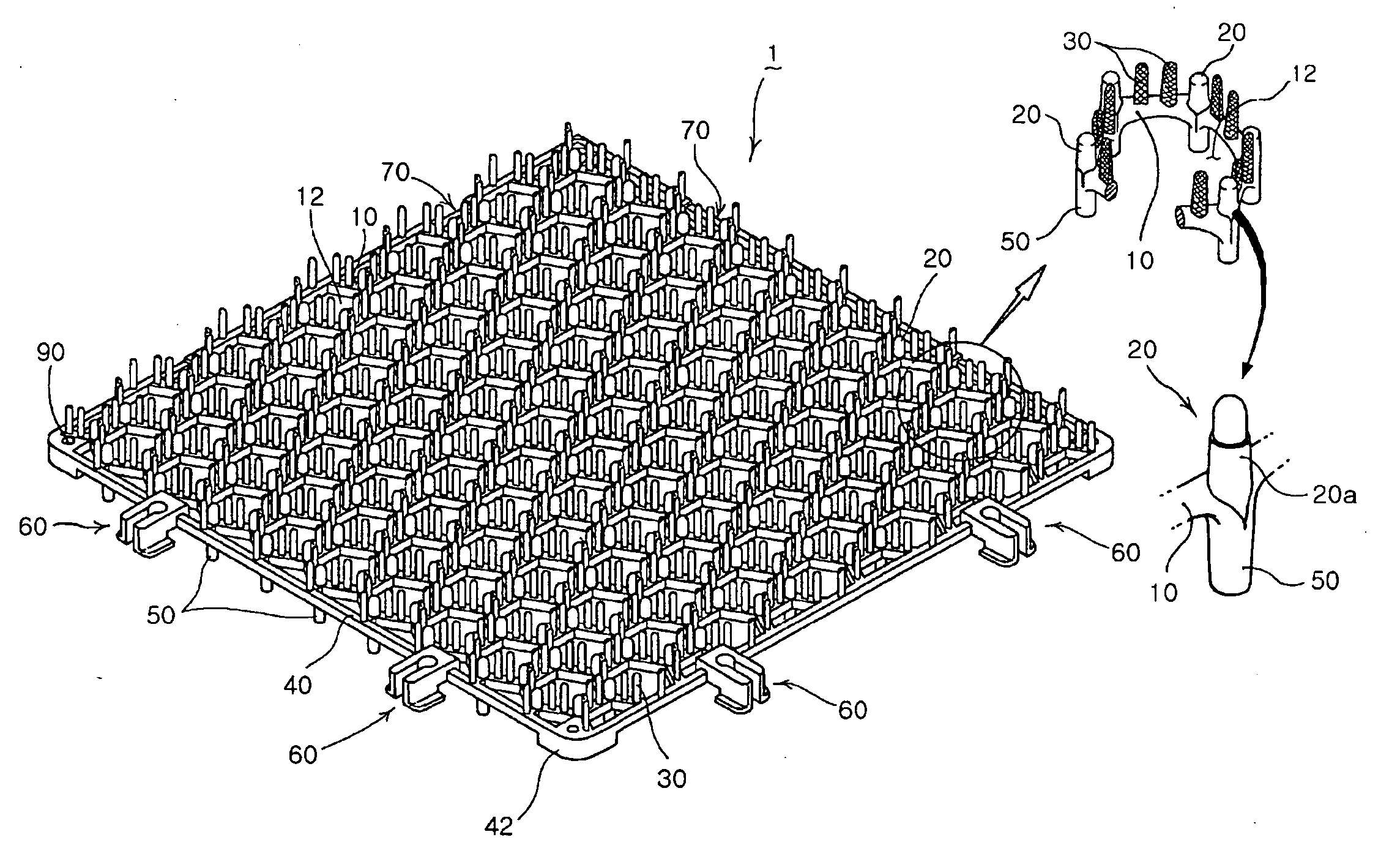
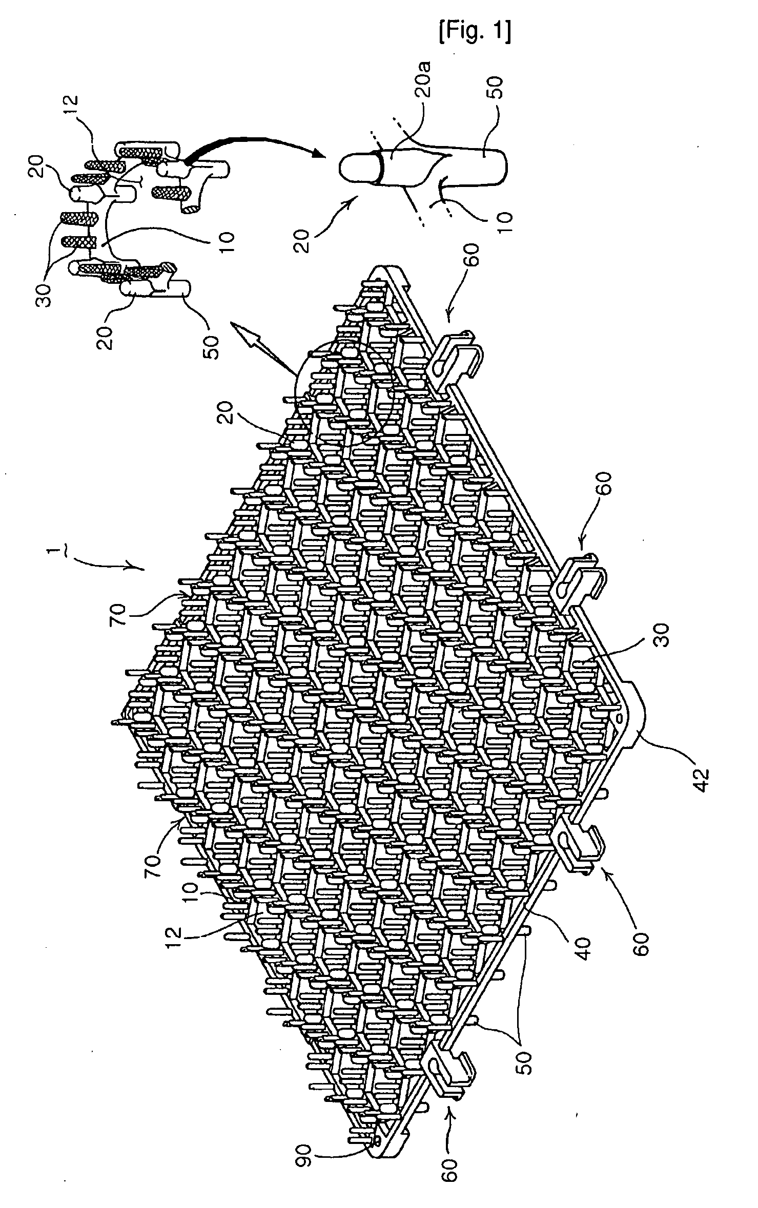
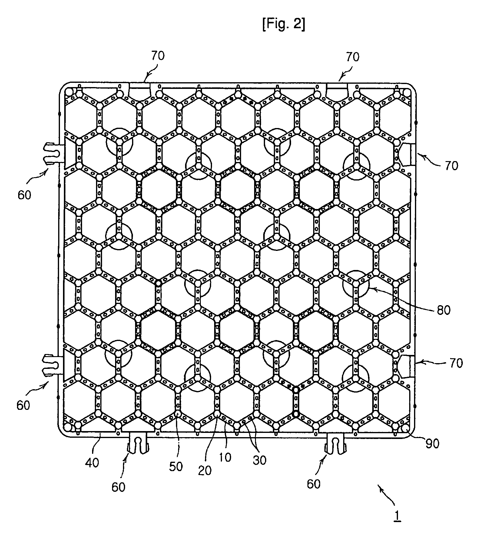
[0060] FIGS. 1 to 3 show the overall constitution of a grass protection mat 1 of the present invention.

[0061] The grass protection mat 1 of the present invention includes body portions 10, pillars 20, buffer wings 30, an outer frame 40, lug members 50, hooking means 60 and openings 70, which will be explained in detail below.

[0062] First, as shown in FIGS. 1 and 2, the hexagonal body portions 10 of the grass protection mat 1 are connected together to provide spaces as large as possible for growth of grass. The body portions 10 provide hexagonal grass reception areas 12 and constitute a frame for maintaining the strength of the mat.

[0063] The body portions 10 may also be composed of an octagonal shape as will be shown in the forthcoming FIG. 9 or a square shape although not shown in separate diagrams.

[0064] The hexagonal body portions 10 provide the grass reception areas 12 of maximum space for the grass to be protected and grown in the facilitated photosynthetic condition.

[0065...


PUM


Abstract

A grass protection mat and a mat assembly having the same are provided. The grass protection mat of the invention includes a body made of polygonal portions, pillars protruded upward from the body, buffer wings protruded upward from the body between the pillars for distributing weights, an outer frame at the periphery of the body, lug members protruded from lower parts of the body and the outer frame. The mat also includes slide-type hooking means laterally protruded for connection of the mats, an opening formed at the inner surface of the outer frame. The mat assembly includes various forms of mat fastening members for connecting the grass protection mats. The invention facilitates connection of the mats and enhances assemblability of the mat assembly, effectively preventing sinking of the mats into the ground, thereby maintaining protection of grass.

Description

TECHNICAL FIELD [0001] The present invention relates to a grass protection mat used for protection of grass in a golf course, a grass ballpark, and a lawn, and more particularly, to a grass protection mat which is easily interconnected with other mats and installed on the ground and which does not sink easily into the ground, and a mat assembly having the same. BACKGROUND ART [0002] In the places where grass is grown, such as golf courses, grass ballparks or parks, grass is easily pressed down and damaged in the area which is subject to human or vehicular traffic (e.g. a golf cart). Repairing the damaged grass requires considerable amount of costs. [0003] In order to uphold and buffer the load of people or vehicles in such an area, grass protection mats have been used, and these mats are well-known in general. [0004] Although not shown in a separate diagram, a generally known conventional grass protection mat includes a body forming an overall structure of the mat, a lug member prov...

Claims


Application Information

Patent Timeline
IPC IPC(8): A01G13/02
CPCA63C19/04E01C5/005Y10T403/60E01C13/083E01C9/004
Inventor SON, CHANG-SUBKIM, SANG-GEUN
Owner SON GYEUL
Learn More