Heat Exchanger

a technology of heat exchanger and heat exchange tube, which is applied in the direction of indirect heat exchanger, lighting and heating apparatus, transportation and packaging, etc., can solve the problems of increasing the overall internal volume of the inlet header, the difficulty of further improving the performance of the evaporator, and the inability to heat exchange the tube. the effect of simple work

Inactive Publication Date: 2008-03-06
KEIHIN THERMAL TECH CORP
View PDF11 Cites 18 Cited by
  • Summary
  • Abstract
  • Description
  • Claims
  • Application Information

AI Technical Summary

Benefits of technology

[0036] With the heat exchanger according to par. 14), the flow dividing control means and the partition means are integral with

Problems solved by technology

However, the present inventor has conducted extensive research and consequently found that it is difficult to further improve the performance of the evaporator disclosed in the above publication for the reasons to be described below.
On the other hand, however, this increases the overall internal volume of the inlet header in which heat exchange tube ends are positioned.
The evaporator is therefore likely to become slower in responsiveness to the turnin

Method used


Image

  • Heat Exchanger
  • Heat Exchanger
  • Heat Exchanger

Examples


Embodiment Construction

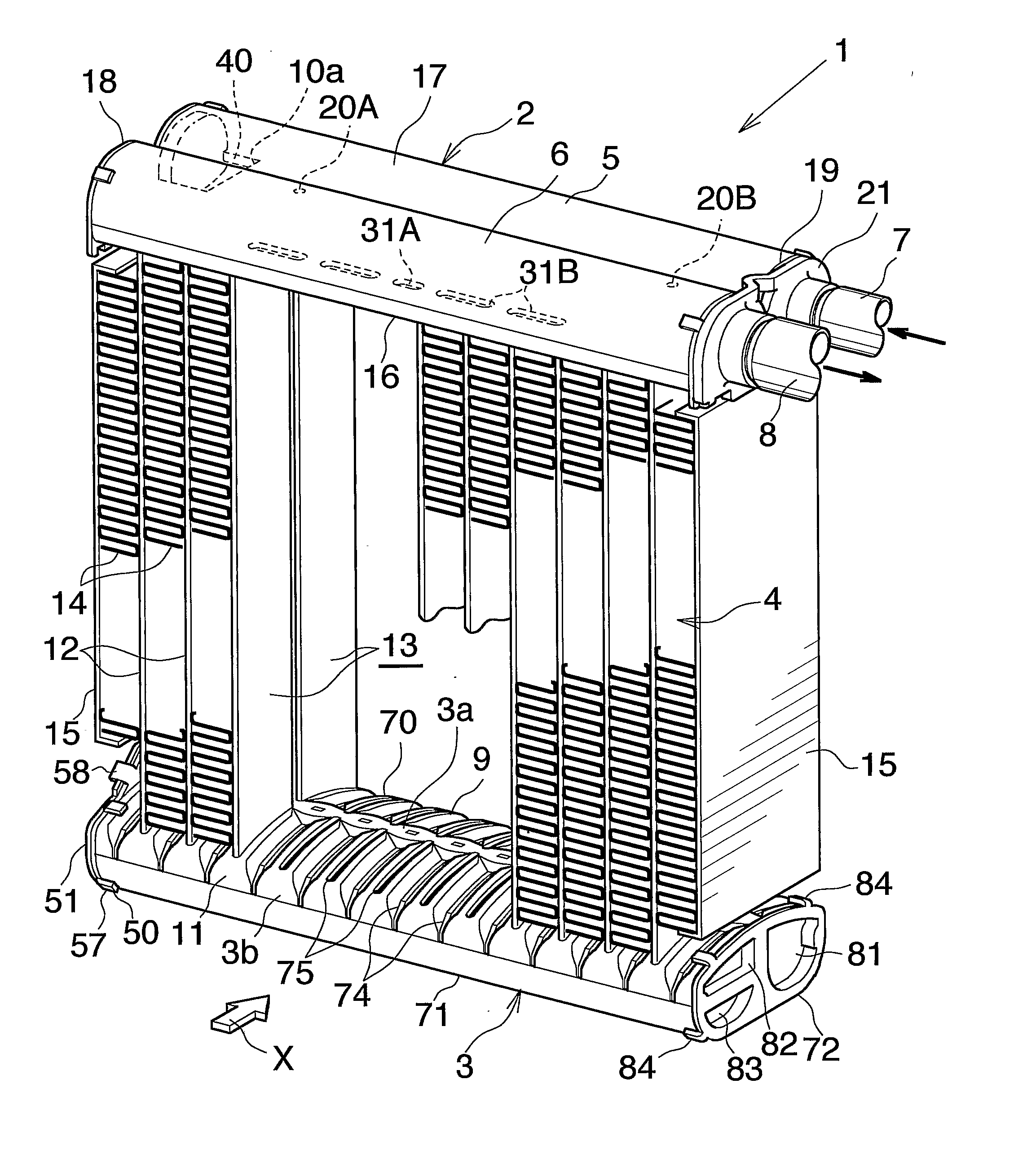
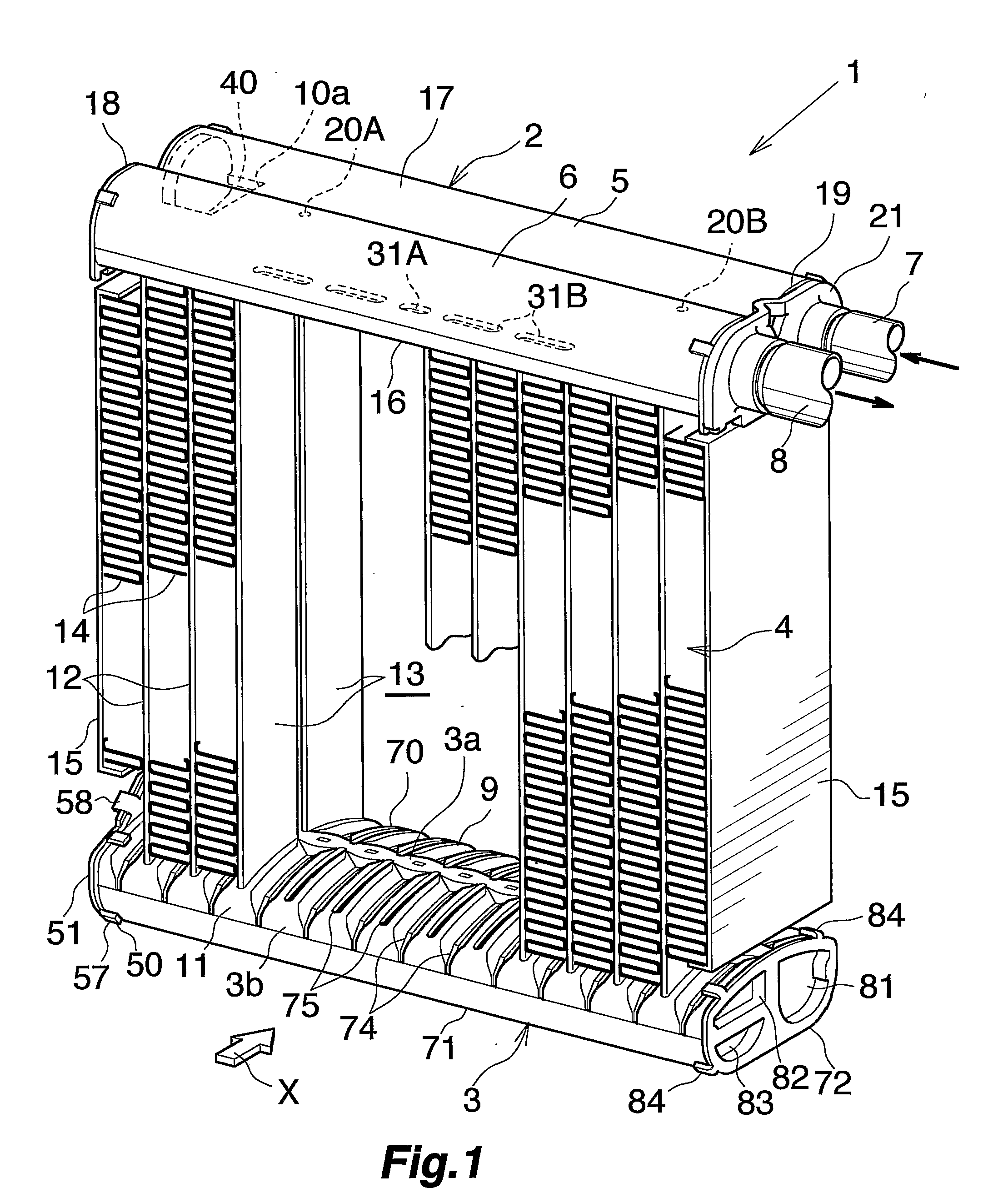
[0046] An embodiment of the present invention will be described below with reference to the drawings. This embodiment is a heat exchanger of the invention as adapted for use as an evaporator in motor vehicle air conditioners wherein a chlorofluorocarbon refrigerant is used.

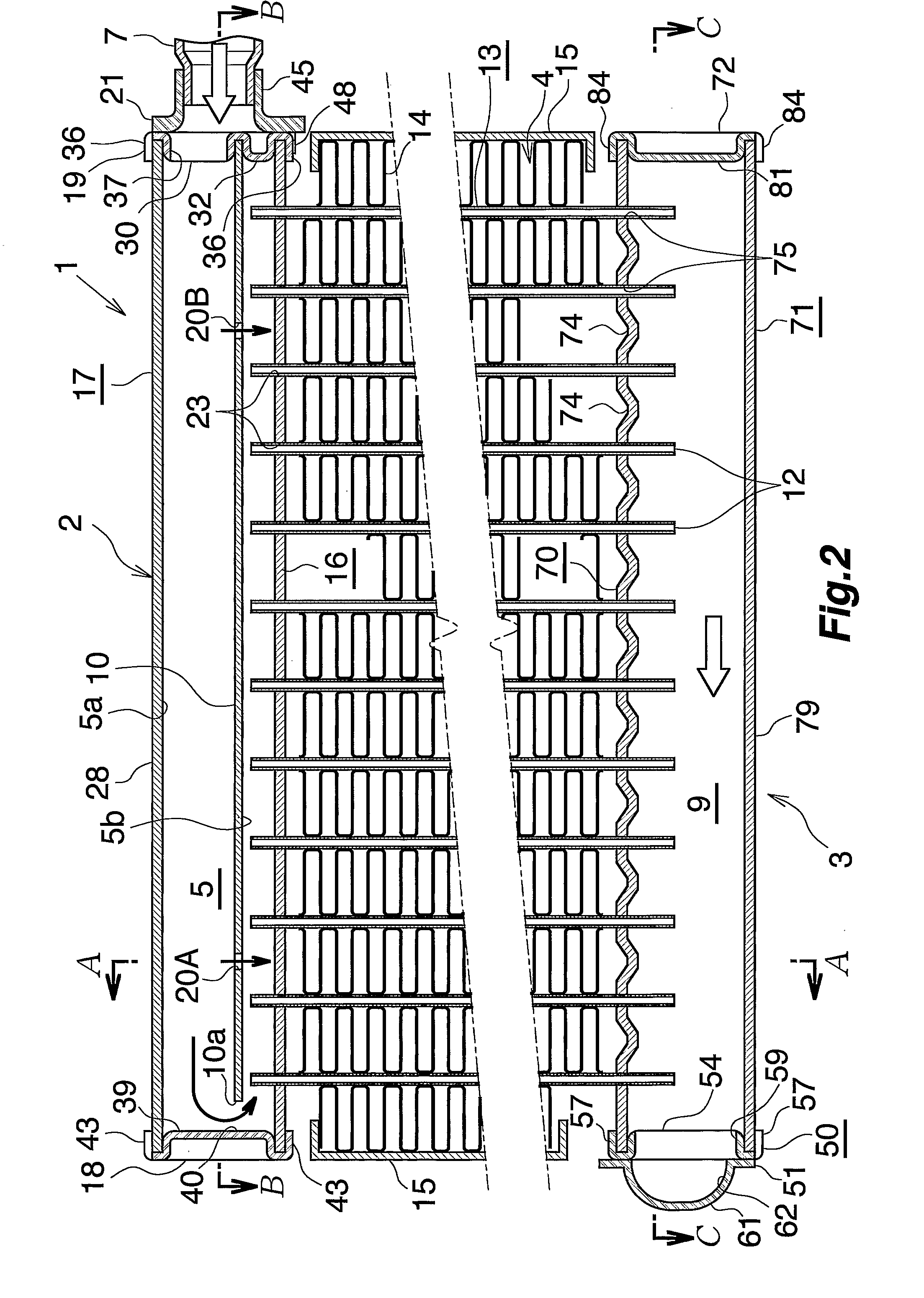
[0047] In the following description, the upper and lower sides and left-hand and right-hand sides of FIGS. 1 and 2 will be referred to as “upper,”“lower,”“left” and “right,” respectively.

[0048] FIGS. 1 to 3 show the overall construction of an evaporator, FIGS. 4 to 8 show the constructions of main parts, and FIG. 9 shows how a refrigerant flows through the evaporator.

[0049] FIGS. 1 to 3 show an evaporator 1, which comprises a refrigerant inlet-outlet header tank 2 of aluminum and a refrigerant turn header tank 3 of aluminum which are arranged one above the other as spaced apart, and a heat exchange core 4 provided between the two tanks 2, 3.

[0050] The refrigerant inlet-outlet header tank 2 comprises a refriger...


PUM


Abstract

An evaporator including a refrigerant inlet header having a refrigerant inlet at one end thereof, and a plurality of heat exchange tubes arranged at a spacing longitudinally of the inlet header and each having one end joined to the inlet header. The interior of the inlet header is divided by a flow dividing control wall into an upper space for admitting a refrigerant thereinto through the refrigerant inlet and a lower space communicating with the heat exchange tubes. The control wall has a communication hole formed in an end portion thereof opposite to the refrigerant inlet. The upper and lower spaces communicate with each other through the communication hole so that the refrigerant flows through the lower space in a direction opposite to the direction of flow of the refrigerant in the upper space. The evaporator achieves a high heat exchange efficiency.

Description

CROSS REFERENCE TO RELATED APPLICATIONS [0001] This application is an application filed under 35 U.S.C. §111(a) claiming the benefit pursuant to 35 U.S.C. §119 (e) (1) of the filing dates of Provisional Applications No. 60 / 588,986 and No. 60 / 618,190 filed Jul. 20, 2004 and Oct. 14, 2004, respectively, pursuant to 35 U.S.C. §111(b).TECHNICAL FIELD [0002] The present invention relates to heat exchangers, more particularly to heat exchangers suitable to use, for example, as evaporators in motor vehicle air conditioners which are refrigeration cycles to be installed in motor vehicles. [0003] The term “aluminum” as used herein and in the appended claims includes aluminum alloys in addition to pure aluminum. [0004] The downstream side (the direction indicated by the arrow X in FIG. 1) of the flow of air to be passed through air passage clearances between respective adjacent pairs of heat exchange tubes of the heat exchanger will be referred to herein and in the appended claims as “front,”...

Claims


Application Information

Patent Timeline
IPC IPC(8): F25B13/00
CPCB60H1/00335F25B39/02F28F9/0278F28D2021/0085F28F9/0214F28D1/05391
Inventor HIGASHIYAMA, NAOHISA
Owner KEIHIN THERMAL TECH CORP
Why Eureka
Try Eureka