One-piece flexible tube connector and method of making the same

Inactive Publication Date: 2008-03-06
SUNSPRING AMERICA
View PDF31 Cites 5 Cited by
  • Summary
  • Abstract
  • Description
  • Claims
  • Application Information

AI Technical Summary

Benefits of technology

[0004]The present invention includes a one-piece flexible tube connector and method for making the same. The one-piece flexible tube connector includes a portio

Problems solved by technology

Therefore, known supply tubes require assembly to attach fittings, which can be costly.
In addition,

Method used


Image

  • One-piece flexible tube connector and method of making the same
  • One-piece flexible tube connector and method of making the same
  • One-piece flexible tube connector and method of making the same

Examples


Embodiment Construction

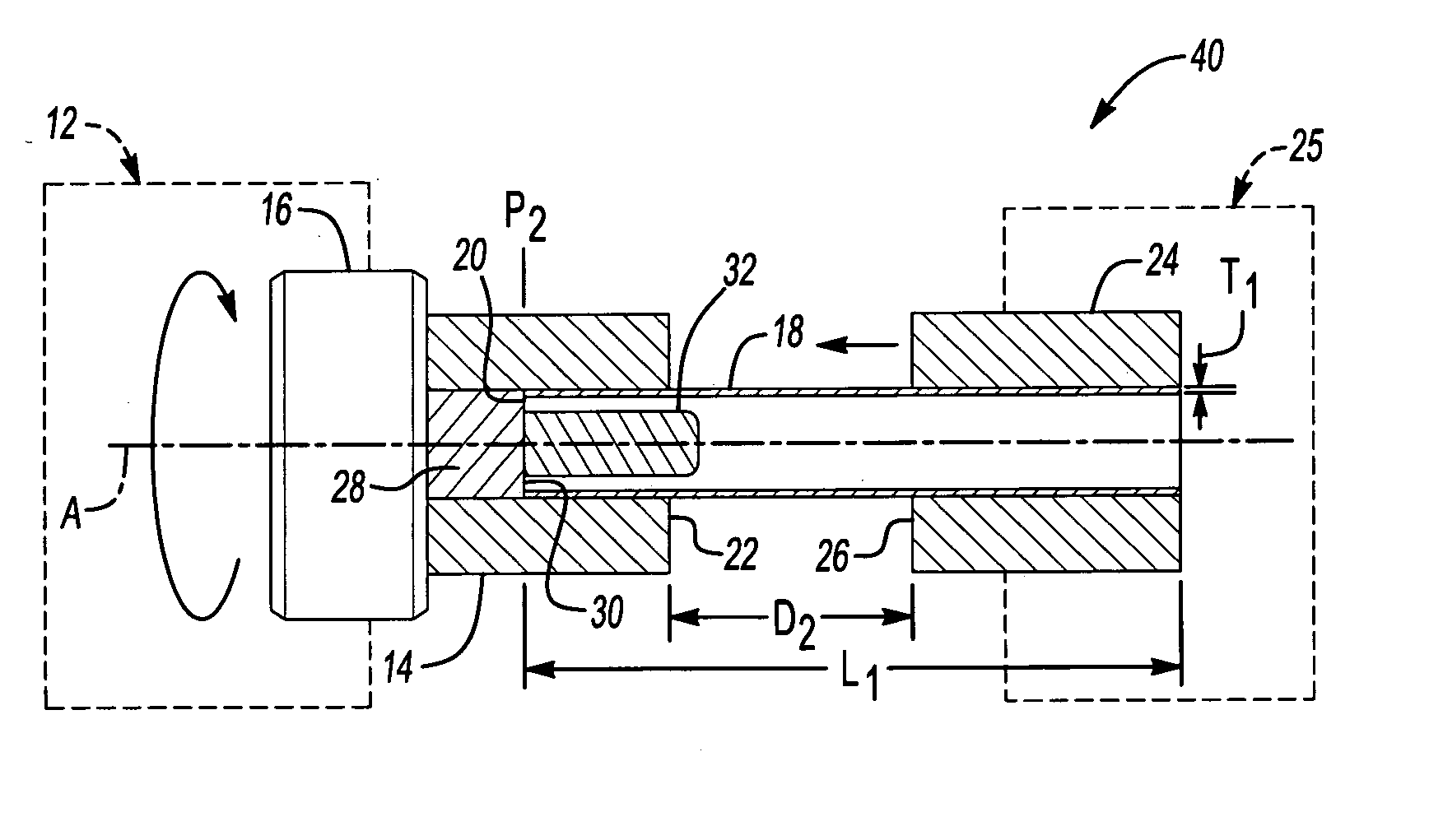
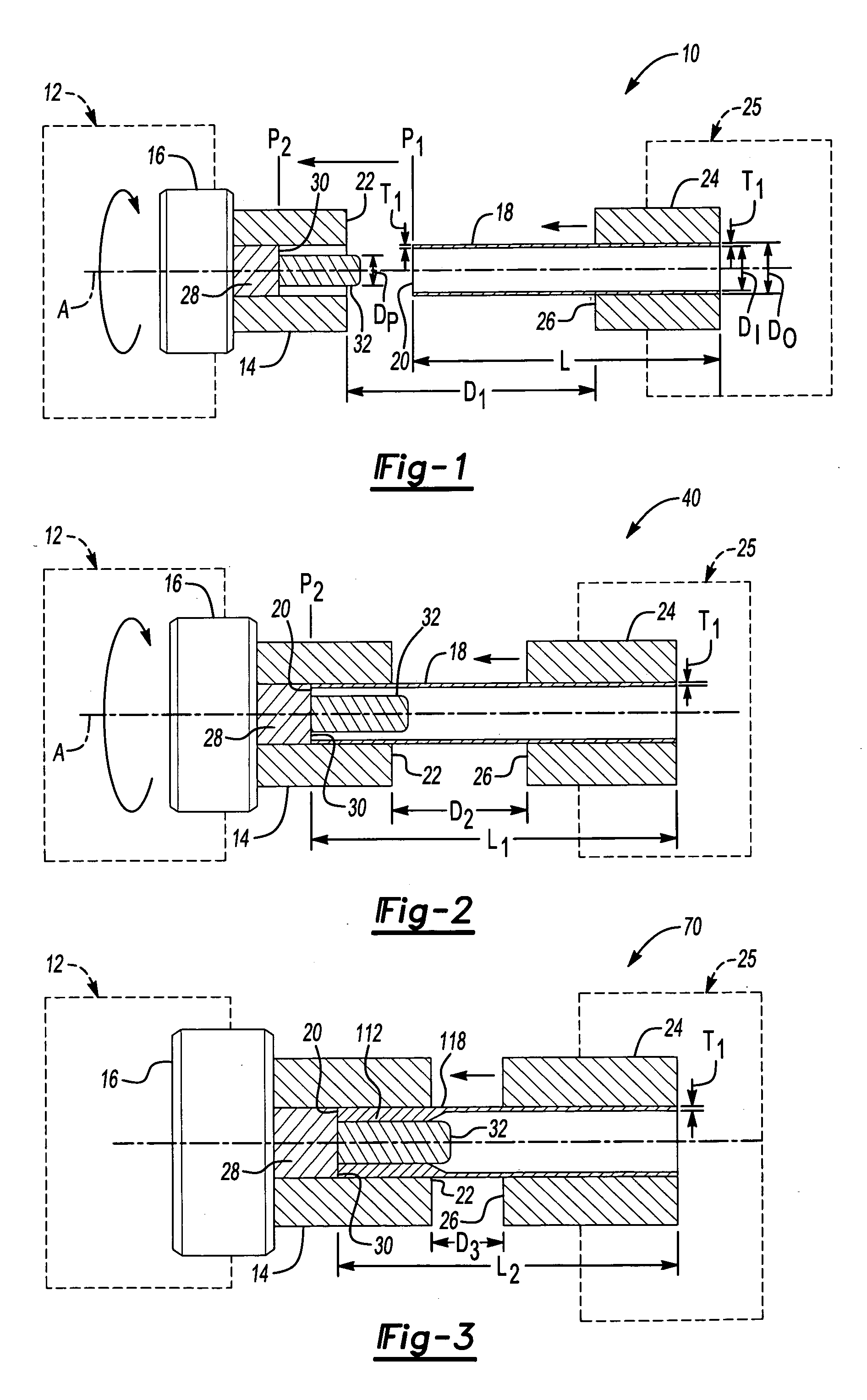
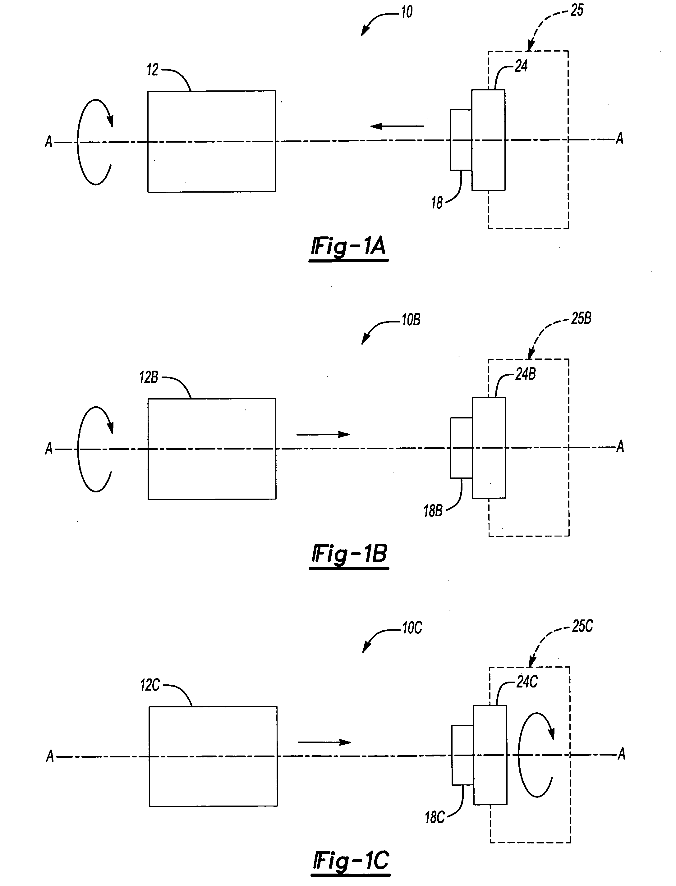
[0019]FIG. 1 schematically illustrates an example tooling set-up 10 for manufacturing a one-piece flexible tube connector (FIG. 6) according to the present invention. A forming machine 12, for example a spinning tool, includes a spinning collar 14 attached to a powered spindle 16, which in this example, rotates in a clockwise manner about an axis A-A. A tube blank 18 is secured in a first horizontal position P1, in which a first end 20 of the tube blank 18 is spaced away from an open end 22 of the spinning collar 14 longitudinally along the axis A-A. The tube blank 18 is secured in the first horizontal position P1 by a clamping device 24, such as a split set of clamp blocks or compressive jaws. In the first horizontal position P1, a leading face 26 of the clamping device 24 is spaced a distance D1 away from the open end 22 of the spinning collar 14. A stop block 28 including a stop surface 30 is disposed within the spinning collar 14. A pilot 32 extends longitudinally outward from t...


PUM

PropertyMeasurementUnit
Lengthaaaaaaaaaa
Thicknessaaaaaaaaaa
Diameteraaaaaaaaaa

Abstract

A method of manufacturing a one-piece flexible tube connector includes obtaining a tube blank having an initial length, an initial outer diameter, and an initial wall thickness. The tube blank is secured in a fixture and fed longitudinally into a forming tool. During the forming process, one of the tube blank and the forming tool is spun increasing an initial wall thickness of a portion of the tube blank to a second wall thickness, while the initial outer diameter of the tube blank is controlled. The thickened portion of the tube blank extends along a second length of the tube blank that is less than the initial length. After the spinning process, an attachment feature, such as a barbed feature, is formed or machined into the thickened portion of the tube blank to produce the one-piece flexible tube connector.

Description

BACKGROUND OF THE INVENTION[0001]The present invention is directed to a one-piece flexible tube connector and method of manufacture.[0002]Metal supply tubes are typically used with flexible supply tubing for plumbing applications including water supply systems. Known supply tubes typically consist of a two-piece assembly produced by attaching a fitting onto an end of a thin wall tube. Each fitting is attached to a tube by any of various known methods such as brazing, threading, for example. A separate fitting is attached to the tube because traditional fittings typically include barbed configurations that are too deep to be cut or stamped directly into the thin wall tube. Known fittings typically include barbed configurations that require a wall thickness of approximately 0.112-0.115 inches to accommodate machining the geometry associated with a typical fitting, while a typical thin wall tube used in a water supply system only has wall thickness of 0.040 inches. Therefore, known sup...

Claims


Application Information

Patent Timeline
IPC IPC(8): B21D51/02
CPCB21D19/14B21K21/12B21J5/08B21J5/063
Inventor KNIRK, GARY LEESHEPPARD, SCOTT S.CRAWFORD, GARY ORELYN
Owner SUNSPRING AMERICA
Why Eureka
Try Eureka