Clutch

a technology of clutches and weights, applied in the field of clutches, can solve the problems of unstable transmission of power, often in a non-constant speed rotation of the base, etc., and achieve the effects of increasing the added value of the clutch, facilitating smoothness and stability of power transmission, and enhancing the engaging force of each clutch weigh

Active Publication Date: 2008-03-06
TUAN HEUI +2
View PDF1 Cites 19 Cited by
  • Summary
  • Abstract
  • Description
  • Claims
  • Application Information

AI Technical Summary

Benefits of technology

[0008]As such, with the practice of the above discussed techniques, the base plate assembly in accordance with the present invention, when put in a gradually increasing speed condition, enhances the engaging force of each clutch weight against a rim of a driven disk by means of a pressing effect induced by the variation of displacement that the respective constraint section takes to engage an inner abutting face of the engaging slot of the clutch weight when the constraint section receives torque from an engine and the solid engaging process ensures an anti-reversal function, which facilitates smoothness and stability of power transmission so as to increase added value of a clutch product and to enhance market competitively and economic value.

Problems solved by technology

However, in practice, the base is often in a non-constant speed rotation due to the fact that the rotational speed of the driven pulley is subject to variation by different operations of the acceleration pedal in response to different driving conditions.
Thus, during the outward expansion and inward closing process, the clutch weight is subject to unstable expansion, leading to oscillatory phenomena of engaging, which causes the transmission of power unstable.

Method used


Image

  • Clutch
  • Clutch
  • Clutch

Examples


first embodiment

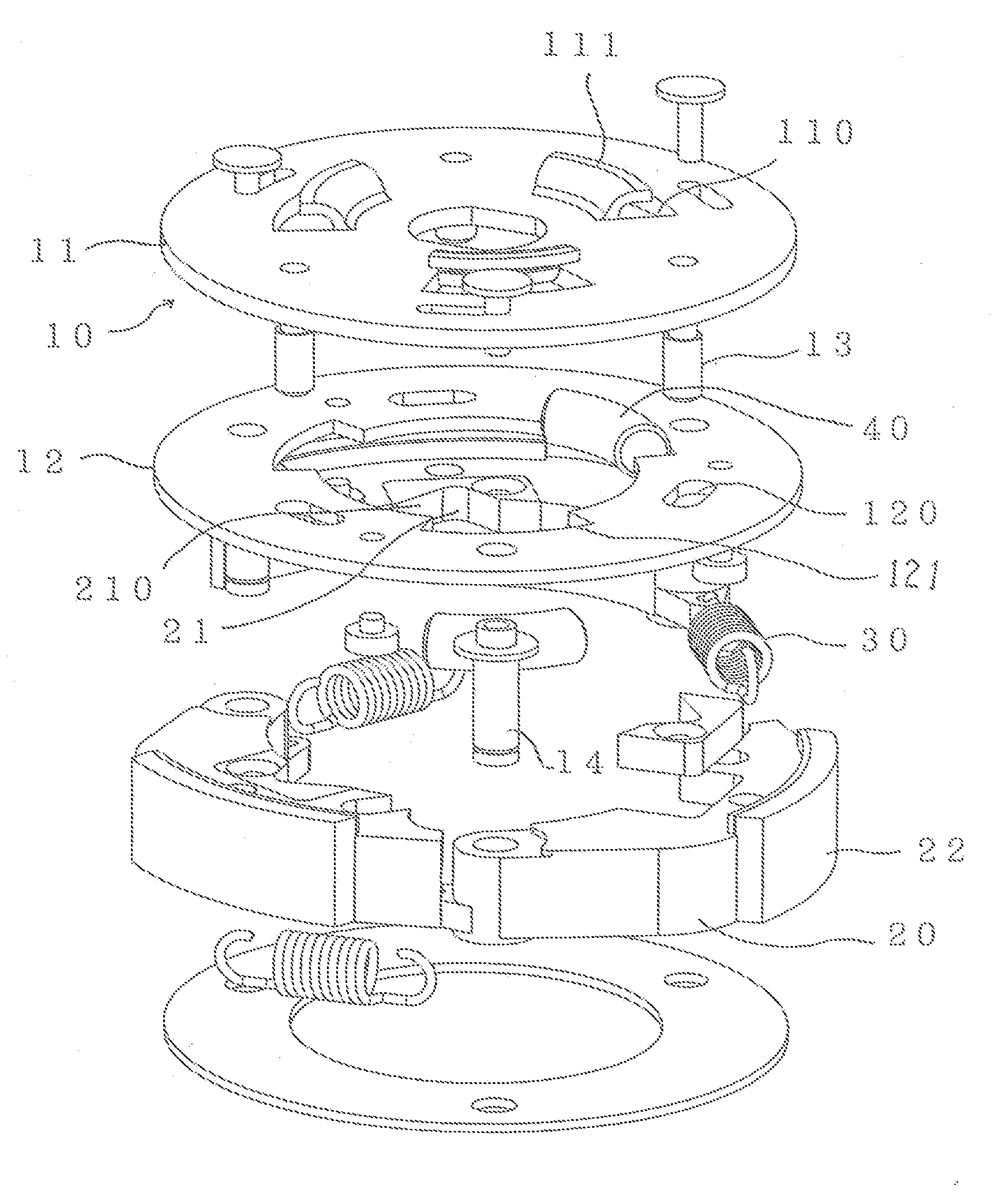
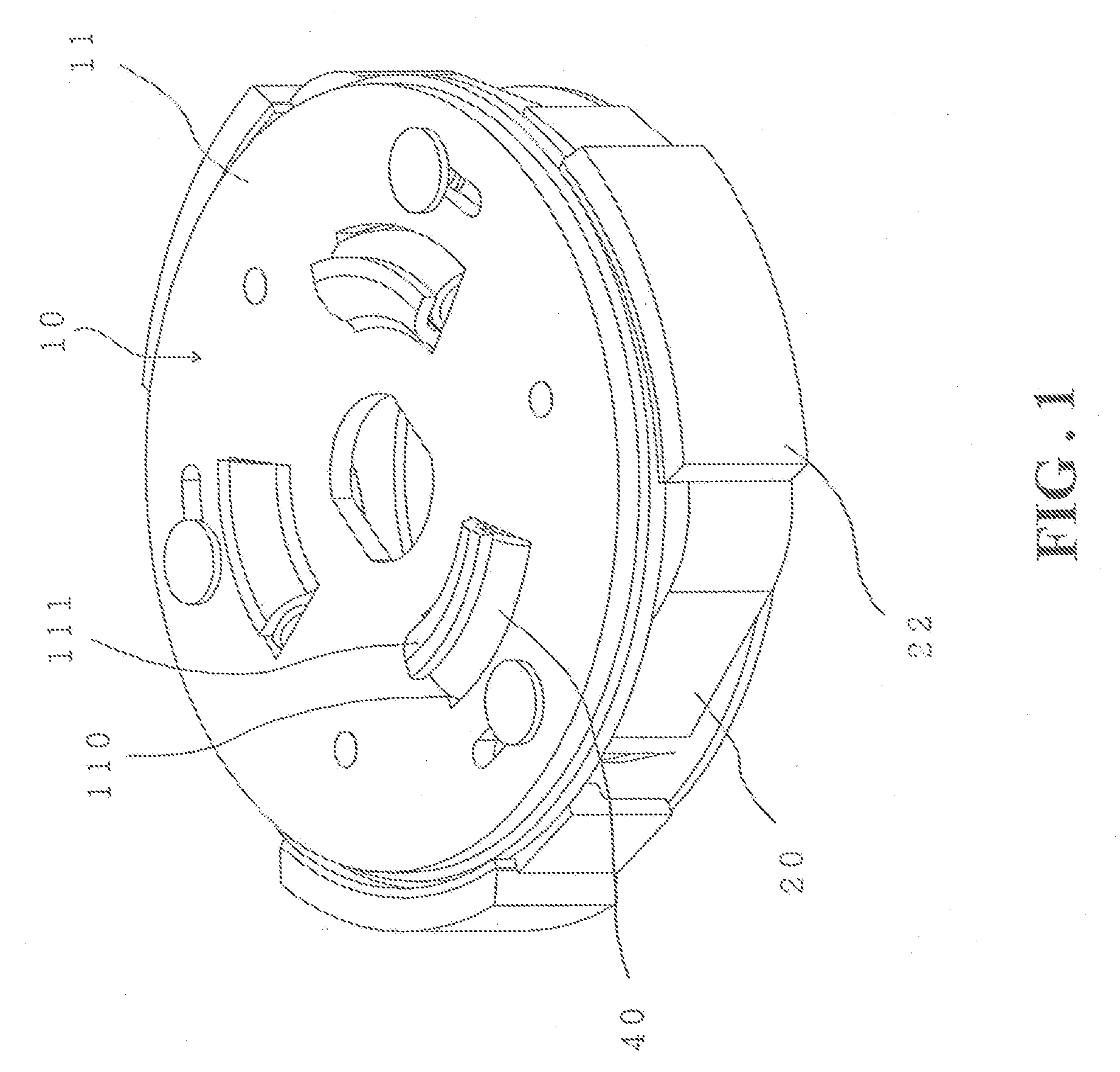
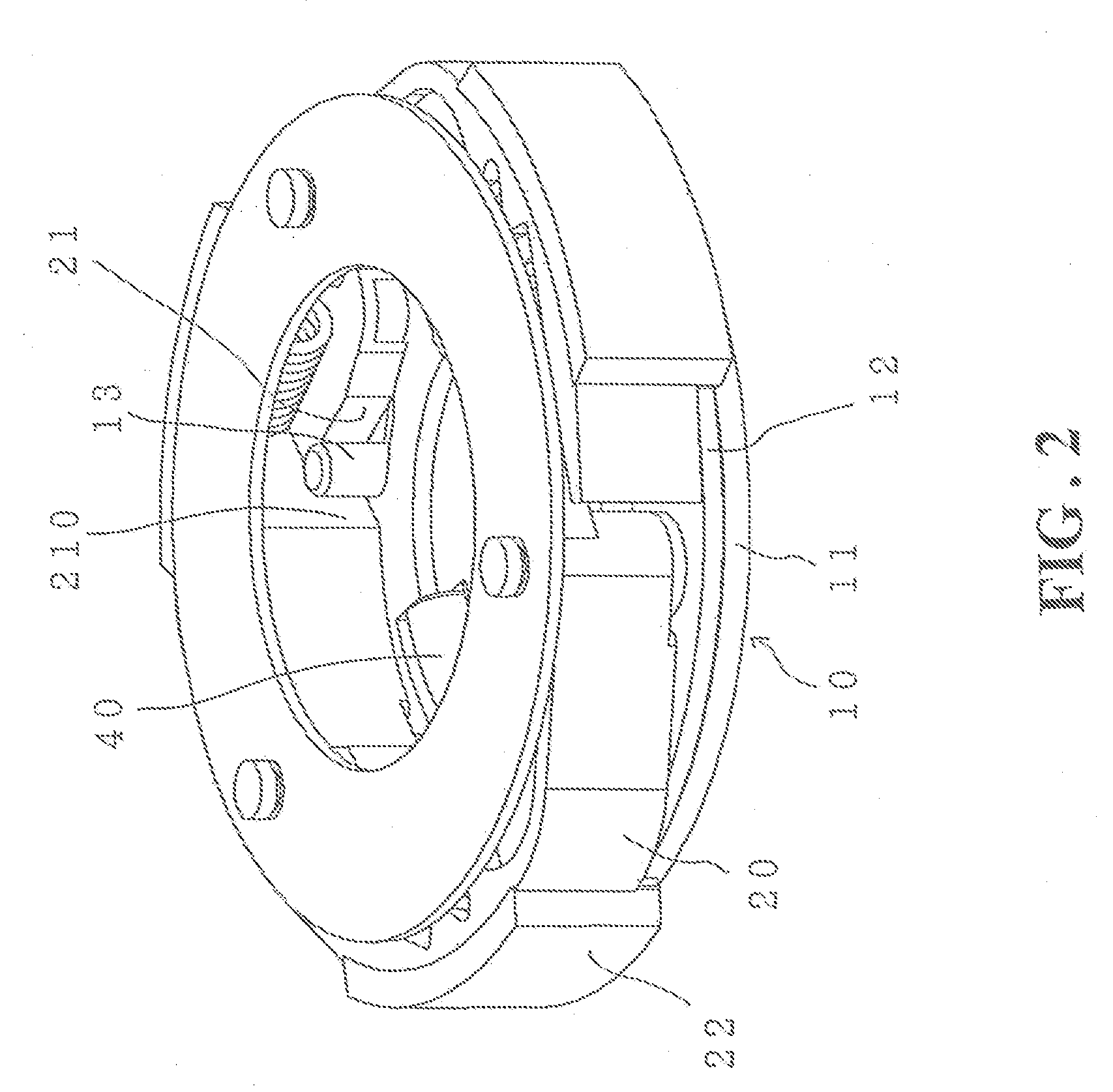
[0037]The above described first embodiment of the present invention can be practiced with excellent result with the following structure, wherein the main driving plate 11 of the base plate assembly 10 is formed with a constraint flange 111 along each mounting slot 110. The constraint flange 111 functions to constrain the intermediate corotating element 40 from separation. The intermediate corotating element 40 is a rubber or plastic bar that is resistant to chemicals and is of high flexibility and compressibility, so that as shown in FIGS. 5-8, when the main driving plate 11 rotates, the intermediate corotating element 40 serves as a medium will be deformed to effect a small angle shifting between the associated driven plate 12 and the main driving plate 11 to thereby enhance the engaging force that the clutch weight 20 applies to the driven disk 50; and when the rotational speed of the base plate assembly 10 is apparently slowed down, the intermediate corotating element 40 efficien...

second embodiment

[0039]Further, based on the practice of the present invention as discussed above, the present invention can achieve the same effect and function with the following second embodiment thereof, which is shown in FIGS. 9-14. The main driving plate 11 of the base plate assembly 10 is provided, on an inside plate surface thereof in an axial direction, with an operation-assisting frame 15 that extends through the associated driven plate 12. The operation-assisting frame 15 is formed, on an inner edge thereof, with a plurality of radially projecting constraint sections 13A at locations corresponding to the clutch weights 20 respectively, and a plurality of hook sections 150. Each hook section 150 is formed with a connecting hole 151. The associated driven plate 12 is formed with a plurality of retention holes 122 corresponding to the connecting holes 151. The paired connecting hole 151 and the retention hole 122, which are respectively formed on the operation-assisting frame 15 of the main ...

third embodiment

[0043]Further, based on the practice of the present invention as discussed above, the present invention can achieve the same effect and function with the following third embodiment thereof, which is shown in FIGS. 16-18. The main driving plate 11 of the base plate assembly 10 is provided with an extended operation-assisting frame 15A and a plurality of intermediate corotating element 40A is arranged between the operation assisting frame 15A and the associated driven plate 12. Thus, the main driving plate 11 that is in rotation can drive the associated driven plate 12 to corotate by means of the operation-assisting frame 15A and the intermediate corotating element 40A. The operation-assisting frame 15A forms a plurality of projecting constraint sections 13A at locations corresponding to clutch weights 20A respectively. The associated driven plate 12 is installed with the clutch weights 20A and each clutch weight formed an engaging slot 21 for being engaged by the projecting constrain...


PUM


Abstract

A clutch having high engaging force and featuring of smooth operation, wherein clutch weights that are biased by return elements are subject to thrusting force caused by constraint sections of a main driving plate that receive and convert torque from an engine into the pressing action against engaging slots defined in the clutch weights so as to gain enhanced engaging force even when the minor difference or error existing on the response time of the clutch weight or the strength of the return elements and also provides anti-reversal function to reduced the oscillation and let the power output more smooth and more stable. Accordingly, slippage of clutch and wear of the clutch wear pad are both reduced and temperature rise of the wear pad is also reduced.

Description

BACKGROUND OF THE INVENTION[0001](a) Technical Field of the Invention[0002]The present invention relates to a clutch that enhances engaging power, and in particular to a clutch of high engaging power and featuring stable engagement, which increases the engaging power of each clutch shoe to smoothen and stabilize power transmission.[0003](b) Description of the Prior Art[0004]A centrifugal clutch is widely used in an automatic transmission mechanism of a motorcycle. The centrifugal clutch functions to reflect the rotational speed of a driven pulley to cause clutch weights that are in pivotal connection with a base to expand the clutch weights, in response to the increasing of rotational speed, for causing the wear pads to engage a rim of a driven disk and thus transmitting power to a driven shaft for driving wheels of motorcycles forward. When the rotational speed is reduced, the clutch weights are moved inward and closed to each other, and the transmission of power to the driven shaf...

Claims


Application Information

Patent Timeline
Patent Type & Authority Applications(United States)
IPC IPC(8): F16D43/14
CPCF16D43/14F16D43/18F16D2043/145
Inventor LEAN, NORMANWU, CHUN-YI
Owner TUAN HEUI
Why Eureka
Try Eureka