Variable valve actuator with latches at both ends

a valve actuator and latch technology, applied in the field of actuators, can solve the problems of inability to meet the requirements of most, if not all, engine valve actuation systems, and the narrow opening window of the cross-over valve has to be extremely narrow, so as to achieve high force and power density, consume too much energy, and achieve high energy efficiency

Inactive Publication Date: 2008-03-06
LGD TECH LLC
View PDF7 Cites 29 Cited by
  • Summary
  • Abstract
  • Description
  • Claims
  • Application Information

AI Technical Summary

Benefits of technology

[0010]In another embodiment, a spring controller allows the engine valve to close at power-off even without sufficient pressure in the cross-over passage.
[0011]The present invention provides significant advantages over the prevailing fluid actuators and their control. Its ability to latch the actuator at both ends is important or critical in applications where an engine valve has to be held at open for a controllable period of time. The fluid nature of the actuator provides high force and power density to deal with the demanding requirement...

Problems solved by technology

Also, the opening window of the cross-over valve has to be extremely narrow, especially at medium a...

Method used


Image

  • Variable valve actuator with latches at both ends
  • Variable valve actuator with latches at both ends
  • Variable valve actuator with latches at both ends

Examples


Embodiment Construction

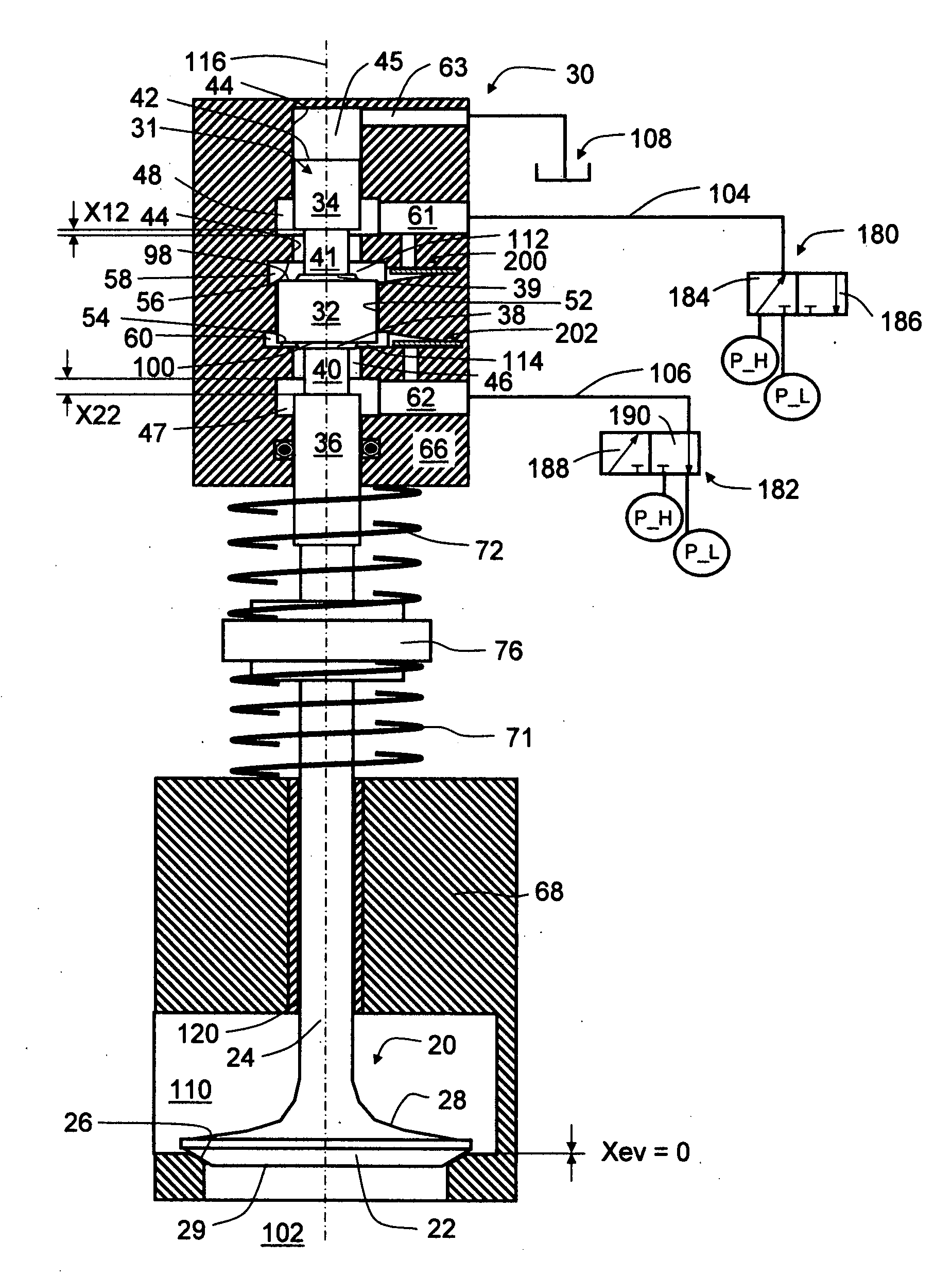
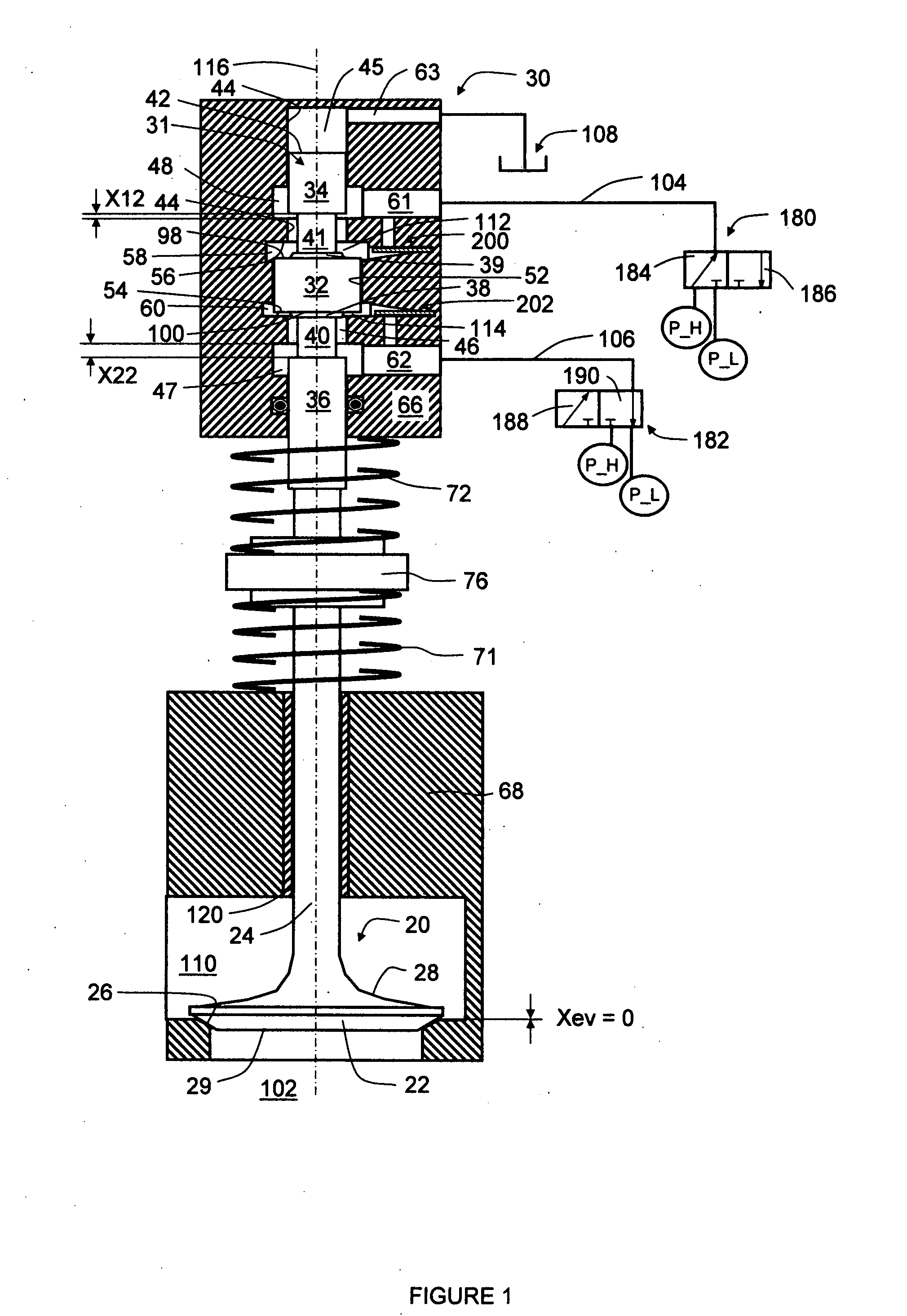
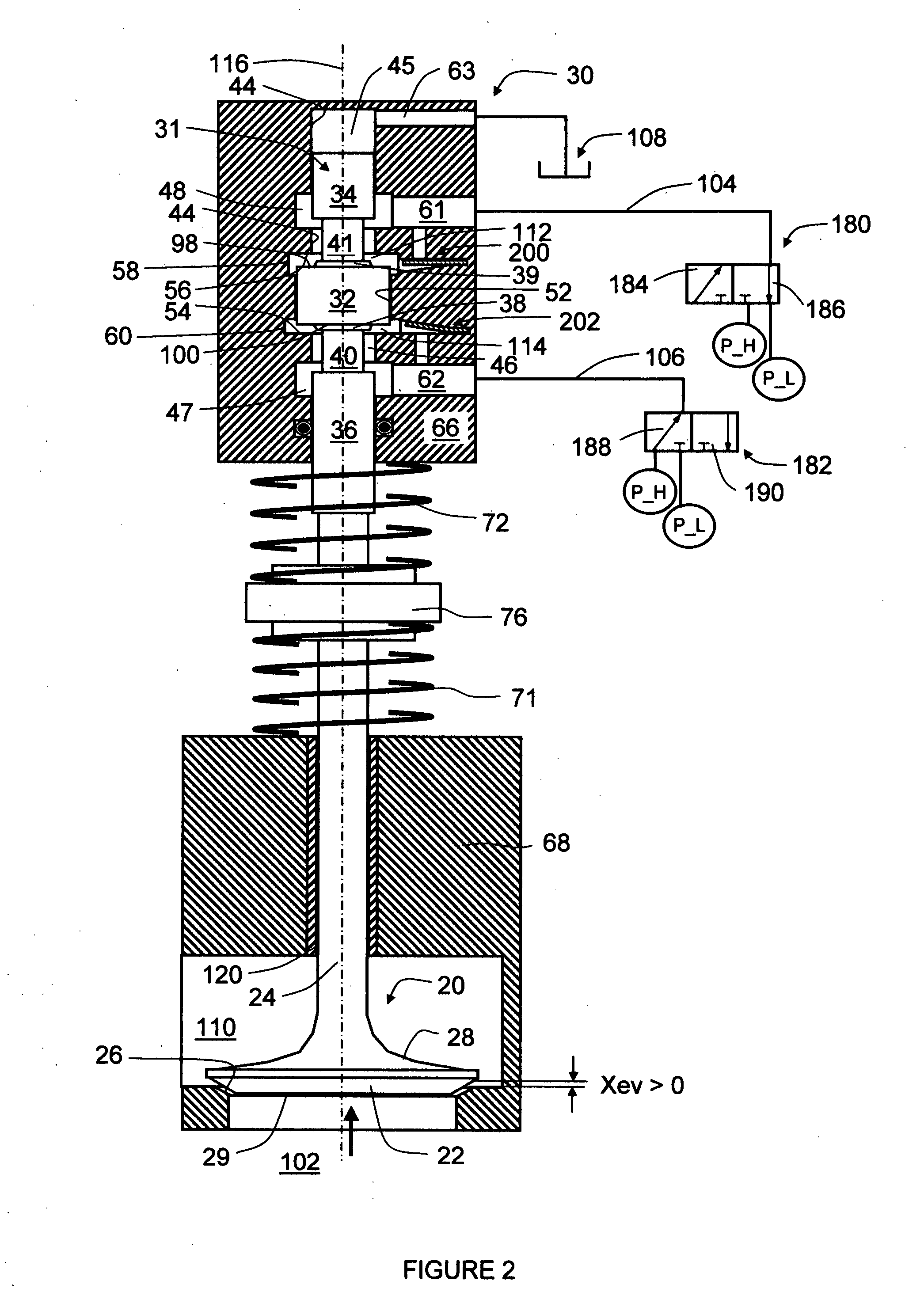
[0020]Referring now to FIG. 1, a preferred embodiment of the invention provides an engine valve control system using one actuation piston, and a set of centering spring means. The system comprises an engine valve 20, a fluid actuator 30, a first actuation 3-way valve 180, a second actuation 3-way valve 182, a pair of actuation springs 71 and 72.

[0021]The first and second actuation 3-way valves 180 and 182 supply the fluid actuator 30 through a first port 61 (via a first-port passage 104) and a second port 62 (via a second-port passage 106), respectively. The first port 61 and the first-port passage 104 may be a physically or functionally continuous part, and so do the second port 62 and the second-port passage 106. Each of the 3-way valves 180 and 182 has two ports connected with a low-pressure P_L fluid line and a high-pressure P_H fluid line, and the third or remaining port connected with one of the two port passages 104 and 106.

[0022]The 3-way valve 180 is switched either to a le...


PUM


Abstract

Actuators and corresponding methods and systems for controlling such actuators offer efficient, fast, flexible control with large forces. In an exemplary embodiment, an fluid actuator includes a housing having first and second fluid ports, an actuation cylinder in the housing defining a longitudinal axis and having first and second ends in first and second directions, an actuation piston in the cylinder with first and second surfaces moveable along the longitudinal axis, a spring subsystem biasing the actuation piston to a neutral position, a first fluid space defined by the first end of the actuation cylinder and the first surface of the actuation piston, and a second fluid space defined by the second end of the actuation cylinder and the second surface of the actuation piston. A first flow mechanism controls fluid communication between the first fluid space and the first port, whereas a second flow mechanism controls fluid communication between the second fluid space and the second port. The first and second flow mechanisms are substantially restricted through two integrated snubbing mechanisms when the actuation piston approaches the first and second direction ends of its travel, respectively. In addition to a differential fluid force on the actuation piston, there is a centering or returning spring force available to help open the engine valve against the high cross-over passage pressure, without the need for the fluid actuation system to be bulky and consume too much energy.

Description

REFERENCE TO RELATED APPLICATION[0001]This application claims priority to Provisional U.S. Patent Application No. 60 / 841,038, file on Aug. 30, 2006, the entire content of which are incorporated herein by reference.FIELD OF THE INVENTION[0002]This invention relates generally to actuators and corresponding methods and systems for controlling such actuators, and in particular, to actuators offering efficient, fast, flexible control with large forces.BACKGROUND OF THE INVENTION[0003]A split four-stroke cycle internal combustion engine is described in U.S. Pat. No. 6,543,225 and U.S. Publication No. US2005 / 0016475A1. It includes at least one power piston and a corresponding first or power cylinder, and at least one compression piston and a corresponding second or compression cylinder. The power piston reciprocates through a power stroke and an exhaust stroke of a four-stroke cycle, while the compression piston reciprocates through an intake stroke and a compression stroke. A pressure cha...

Claims


Application Information

Patent Timeline
IPC IPC(8): F16K31/12
CPCF01L1/462F01L1/465F01L2003/258F01L2001/3443F01L2001/34446F01L9/02F01L9/10
Inventor LOU, ZHENG
Owner LGD TECH LLC
Why Eureka
Try Eureka