Supercharge Your Innovation With Domain-Expert AI Agents!

Plasma display panel

Inactive Publication Date: 2008-03-06
SAMSUNG SDI CO LTD
View PDF5 Cites 0 Cited by
  • Summary
  • Abstract
  • Description
  • Claims
  • Application Information

AI Technical Summary

Benefits of technology

[0006]It is therefore a feature of an embodiment of the present invention to provide a PDP structure exhibiting minimized manufacturing failures upon attachment of a signal transmitting member thereto.

Problems solved by technology

However, application of force to physically connect the signal transmitting member to the discharge electrodes may result in excessive strain on portions of the PDP adjacent to the signal transmitting member, thereby triggering potential manufacturing failures, e.g., deformation and / or breakage of barrier ribs, and an increase of overall manufacturing costs.

Method used


Image

  • Plasma display panel
  • Plasma display panel
  • Plasma display panel

Examples


Embodiment Construction

[0016]Korean Patent Application No. 10-2006-0082305, filed on Aug. 29, 2006, in the Korean Intellectual Property Office, and entitled: “Plasma Display Panel (PDP),” is incorporated by reference herein in its entirety.

[0017]Embodiments of the present invention will now be described more fully with reference to the accompanying drawings, in which exemplary embodiments of the invention are illustrated. Aspects of the invention may, however, be embodied in different forms and should not be construed as limited to the embodiments set forth herein. Rather, these embodiments are provided so that this disclosure will be thorough and complete, and will fully convey the scope of the invention to those skilled in the art.

[0018]In the figures, the dimensions of layers and regions may be exaggerated for clarity of illustration. It will also be understood that when a layer or element is referred to as being “on” another layer, element or substrate, it can be directly on the other layer or substra...


PUM

PropertyMeasurementUnit
Flexibilityaaaaaaaaaa
Electrical conductoraaaaaaaaaa
Photoluminescenceaaaaaaaaaa

Abstract

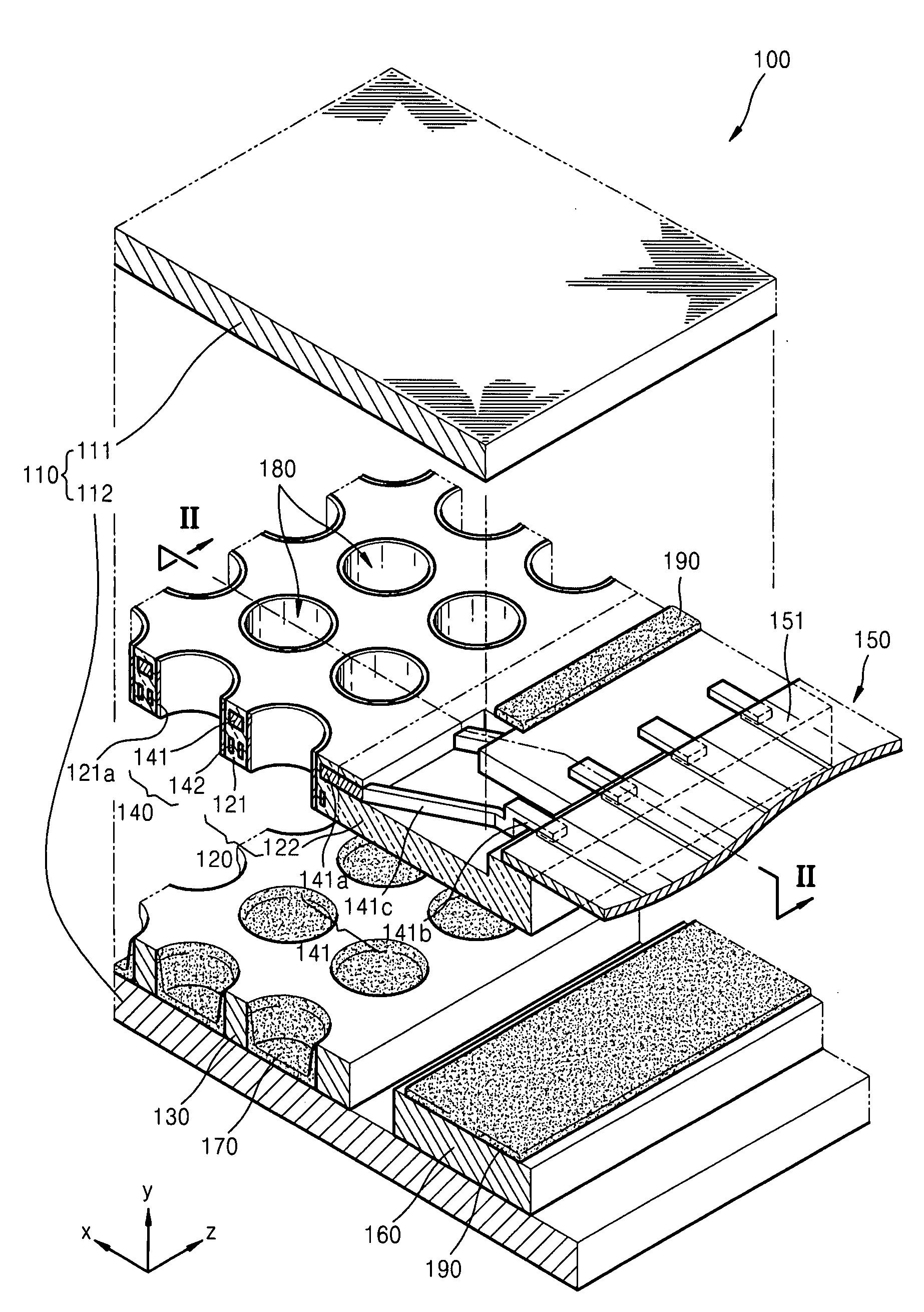
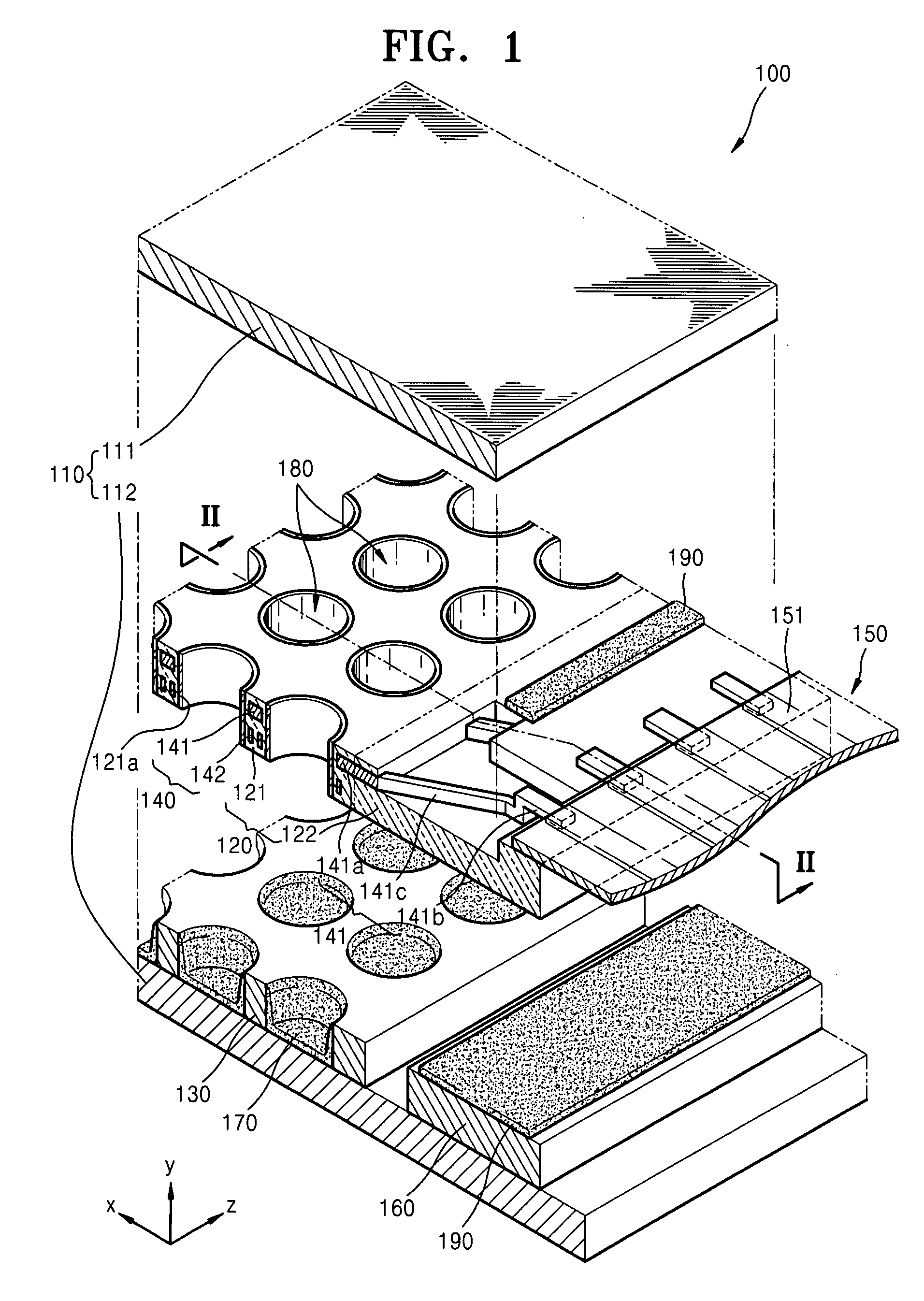
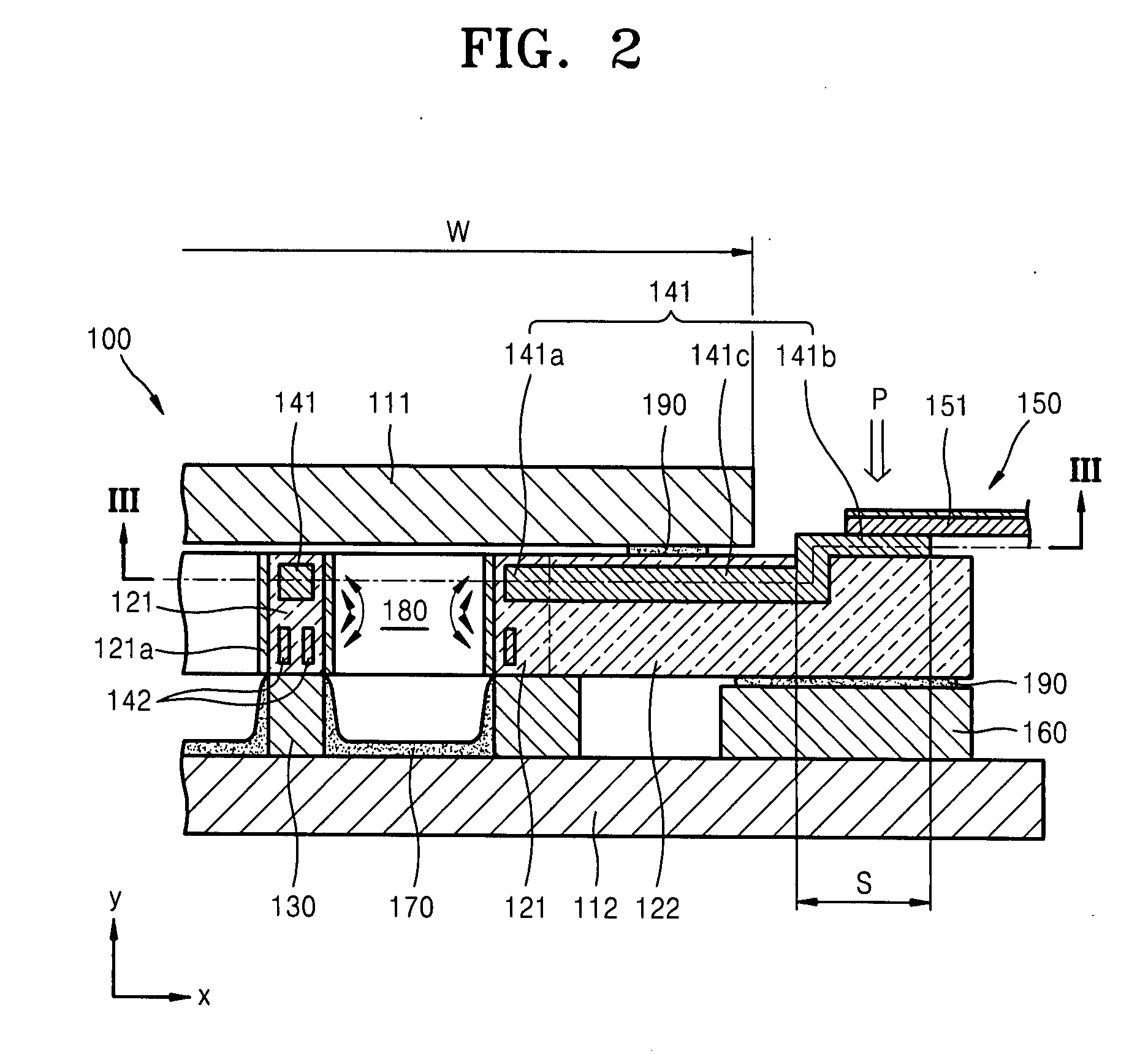
A plasma display panel includes first and second substrates facing each other, a first barrier rib structure between the first and second substrates, the first barrier rib structure including first and second barrier rib portions in communication with each other, a second barrier rib structure on the second substrate, the second barrier rib structure aligned with the first barrier rib portion to define a plurality of discharge cells, a plurality of discharge electrodes, each discharge electrode including a discharge part in the first barrier rib portion, a terminal part in communication with the second barrier rib portion, and a connection part between the discharge and terminal parts, a signal transmitting member with conductive wires, the conductive wires being connected to the terminal parts, a support part between the second substrate and the second barrier rib portion of the first barrier rib structure, and photoluminescent layers in the discharge cells.

Description

BACKGROUND OF THE INVENTION[0001]1. Field of the Invention[0002]Embodiments of the present invention relate to a plasma display panel. More particularly, embodiments of the present invention relate to a plasma display panel having a structure capable of minimizing barrier rib damage upon attachment of a signal transmitting member thereto.[0003]2. Description of the Related Art[0004]Plasma display panels (PDP) refer to display devices capable of displaying images using gas discharge phenomenon, i.e., use of voltage to trigger ultraviolet light and excite a photoluminescent material in order to emit visible light to form images. A conventional PDP may include front and a rear substrates, a plurality of barrier ribs therebetween to define discharge cells with discharge gas, discharge electrodes to facilitate voltage application, and a circuit board to operate the PDP. The discharge electrodes may be electrically connected to the circuit board via a signal transmitting member. However, ...

Claims


Application Information

Patent Timeline
IPC IPC(8): H01J17/49
CPCH01J11/16H01J11/46H01J11/36H01J11/48C03C8/02H01J11/32H01J2211/326
Inventor AHN, HO-YOUNGYI, WON-JUKANG, KYOUNG-DOOLEE, DONG-YOUNGPARK, SOO-HOWOO, SEOK-GYUNKWON, JAE-IK
Owner SAMSUNG SDI CO LTD
Features
  • R&D
  • Intellectual Property
  • Life Sciences
  • Materials
  • Tech Scout
  • Unparalleled Data Quality
  • Higher Quality Content
  • 60% Fewer Hallucinations
Learn More