Touch panel display, electronic apparatus and playing apparatus

a technology of electronic equipment and touch panel display, which is applied in the field of touch panel display, electronic equipment and playing equipment, can solve the problems of increasing power consumption, difficulty in reducing the thickness of the apparatus having the touch panel display, and large power consumption at the time of outputting the sound, so as to reduce the power consumption of the touch panel display and reduce the power consumption of the actuator at the time of generating the sound

Active Publication Date: 2008-03-06
SONY CORP
View PDF6 Cites 125 Cited by
  • Summary
  • Abstract
  • Description
  • Claims
  • Application Information

AI Technical Summary

Benefits of technology

[0013]According to the embodiments of the present invention, the electric power consumed by the actuator at the time of generating a sound can be reduced, as compared with the electric power consumed by the actuator at the time of generating a tactile feedback, which is advantageous in contriving a reduction in the power consumption of a touch panel display.

Problems solved by technology

However, in the touch panel display disclosed in Patent Document 1, an actuator for generating a vibration should be disposed between a touch panel and a display panel, between the display panel and a backlight, or between the backlight and a frame, which makes it difficult to reduce the thickness of the apparatus having the touch panel display.
In that case, however, a quite high driving force may be needed to vibrate the display panel itself, leading to an increase in power consumption.
Besides, in the case where a function of generating a sound by vibrating a liquid crystal display panel is added, a large power consumption may be needed also at the time of outputting the sound.

Method used


Image

  • Touch panel display, electronic apparatus and playing apparatus
  • Touch panel display, electronic apparatus and playing apparatus
  • Touch panel display, electronic apparatus and playing apparatus

Examples


first embodiment

[0020]Now, an embodiment of the present invention will be described below.

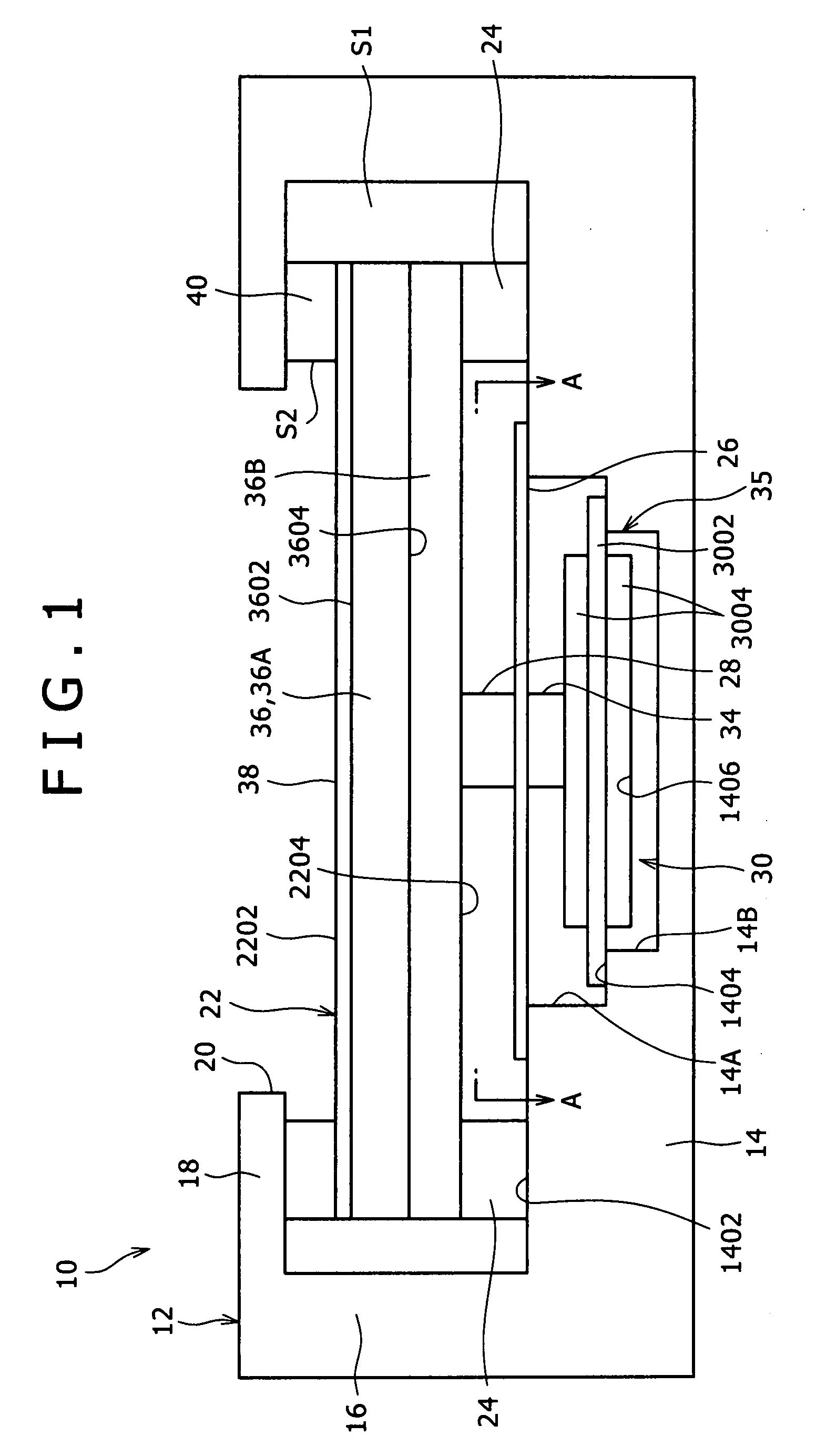
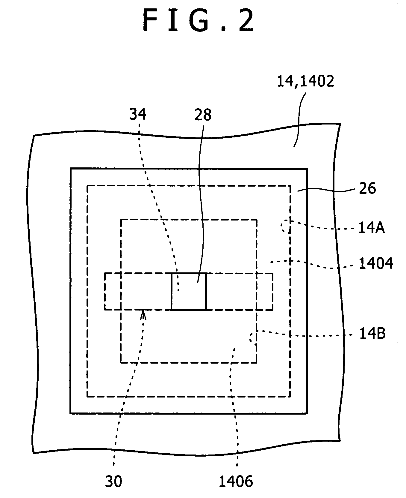
[0021]FIG. 1 is a sectional view showing the configuration of a touch panel display 10 according to an embodiment of the present invention, and FIG. 2 is a view taken along arrowed line A-A of FIG. 1.

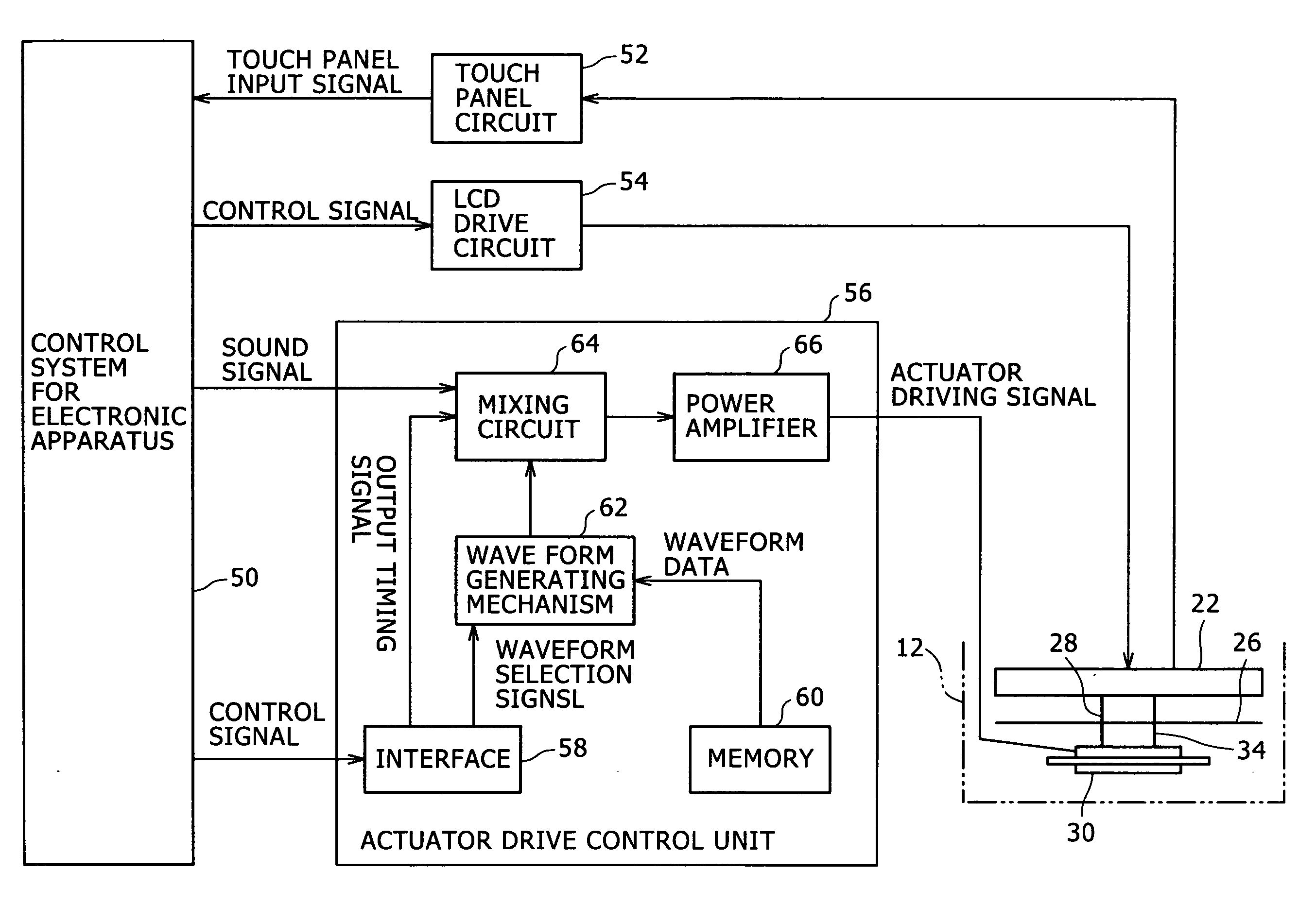
[0022]The touch panel display 10 includes a casing 12 (support structure), a movable panel unit 22, a movable support member 24, a sound generating member 26, a soft member 28, an actuator 30, a hard member 34, an actuator drive control unit 56 (see FIG. 3) and the like.

[0023]As shown in FIG. 1, the casing 12 has a rectangular plate-like bottom wall 14, four side walls 16 rising from the periphery of the bottom wall 14, and a rectangular frame-like upper wall 18 bent from the upper ends of the four side walls 16 toward the inside of the side walls 16 to be parallel to the bottom wall 14. Edge parts of the upper wall 18 define a rectangular opening 20.

[0024]As shown in FIG. 2, a rectangular first recessed part 14A ...

second embodiment

[0088]Now, a second embodiment of the present invention will be described below.

[0089]The second embodiment resides in the application of a touch panel display 10 of the present invention to a playing apparatus (game machine) configured as an electronic apparatus.

[0090]FIGS. 5A and 5B illustrate a playing apparatus 2 according to the second embodiment. Incidentally, in the following description of the embodiment, the equivalent or same parts and members as those in the first embodiment above will be denoted by the same symbols used above.

[0091]The playing apparatus 2 is a so-called arcade game machine installed in a shop such as a game arcade. The playing apparatus 2 shown in FIG. 5A is of the type in which the user plays a game in his standing position, while the playing apparatus 2 shown in FIG. 5B is of the type in which the user plays a game in his seated position.

[0092]As shown in FIGS. 5A and 5B, the playing apparatus 2 has an apparatus-side casing 202, a casing 12 of a touch ...

third embodiment

[0095]Now, a third embodiment of the present invention will be described.

[0096]The third embodiment is different from the second embodiment in the moving direction and vibrating direction at the time when a movable panel unit 22 is depressed.

[0097]FIG. 6 is a sectional view showing the configuration of a touch panel display 70 according to the third embodiment.

[0098]In the third embodiment, the movable panel unit 22 is supported on a support structure (a bottom surface 1402 of a bottom wall 14 of a casing 12) by a movable support member 24 so that it can be displaced along the surface of a touch panel 38.

[0099]In addition, an acoustic vibration unit 35 is provided between the movable panel unit 22 and the support structure (a side wall 16 of the casing 12) in a direction along the surface of the touch panel 38.

[0100]A soft member 28 is provided between the movable panel unit 22 and the acoustic vibration unit 35. The soft member 28 is put into a compressed state when the surface of ...


PUM


Abstract

Disclosed herein is a touch panel display including, a flat plate-shaped movable panel unit, a movable support member, an acoustic vibration unit, and a soft member, wherein the acoustic vibration unit includes, a sound generating member, an actuator, and a hard member.

Description

CROSS REFERENCES TO RELATED APPLICATIONS[0001]The present invention contains subject matter related to Japanese Patent Application JP 2006-231817 filed in the Japan Patent Office on Aug. 29, 2006, the entire contents of which being incorporated herein by reference.BACKGROUND OF THE INVENTION[0002]1. Field of the Invention[0003]The present invention relates to a touch panel display, an electronic apparatus and a playing apparatus (game machine) which each have the touch panel display.[0004]2. Description of the Related Art[0005]A touch panel display used as an input device or an input / output device is advantageous in that an input screen can be freely configured by use of software, and it therefore has a flexibility which cannot be obtained with an input device composed by use of mechanical switches. In addition, the touch panel display can be configured to be light in weight and compact in form, and is low in frequency of occurrence of mechanical failures. Due to these advantages, t...

Claims


Application Information

Patent Timeline
Patent Type & Authority Applications(United States)
IPC IPC(8): G06F3/043A63F13/2145A63F13/24A63F13/25A63F13/285
CPCG06F3/0488G06F3/016
Inventor TAKENAKA, MIKIOMARUYAMA, SHIGEAKI
Owner SONY CORP
Why Eureka
Try Eureka