Sensor device

a sensor and sensor technology, applied in the field of sensor units, can solve the problems of higher power consumption of the compound sensor unit, and achieve the effects of reducing shock, enhancing measurement accuracy, and suppressing acceleration sensor deformation

Active Publication Date: 2007-07-17
MOSAID TECH
View PDF9 Cites 54 Cited by
  • Summary
  • Abstract
  • Description
  • Claims
  • Application Information

AI Technical Summary

Benefits of technology

[0006]In view of the above conventional problem, it is an object of the present invention to provide a sensor unit capable of reducing a space (area) required for mounting a plurality of sensors for measuring physical properties, and reducing the electric power required for driving these sensors.Means for Solving Problems
[0016]In the sensor unit of the present invention, at least one of the plurality of physical-quantity sensors and the signal-processing circuit may be disposed, respectively, on the top and bottom surfaces of the lead in such a manner as to sandwich the lead therebetween. This allows the sensor unit to be reduced in size. In addition, the lead made of metal, such as iron-nickel alloy, is interposed between ICs of the signal-processing circuit and the physical-quantity sensor. Thus, the lead can prevent the physical-quantity sensor from being adversely affected by noises generated from the signal-processing circuit.

Problems solved by technology

However, the conventional compound sensor unit involves a problem concerning higher power consumption because it is designed to drive the pressure sensor and the temperature sensor independently.

Method used


Image

  • Sensor device
  • Sensor device
  • Sensor device

Examples


first embodiment

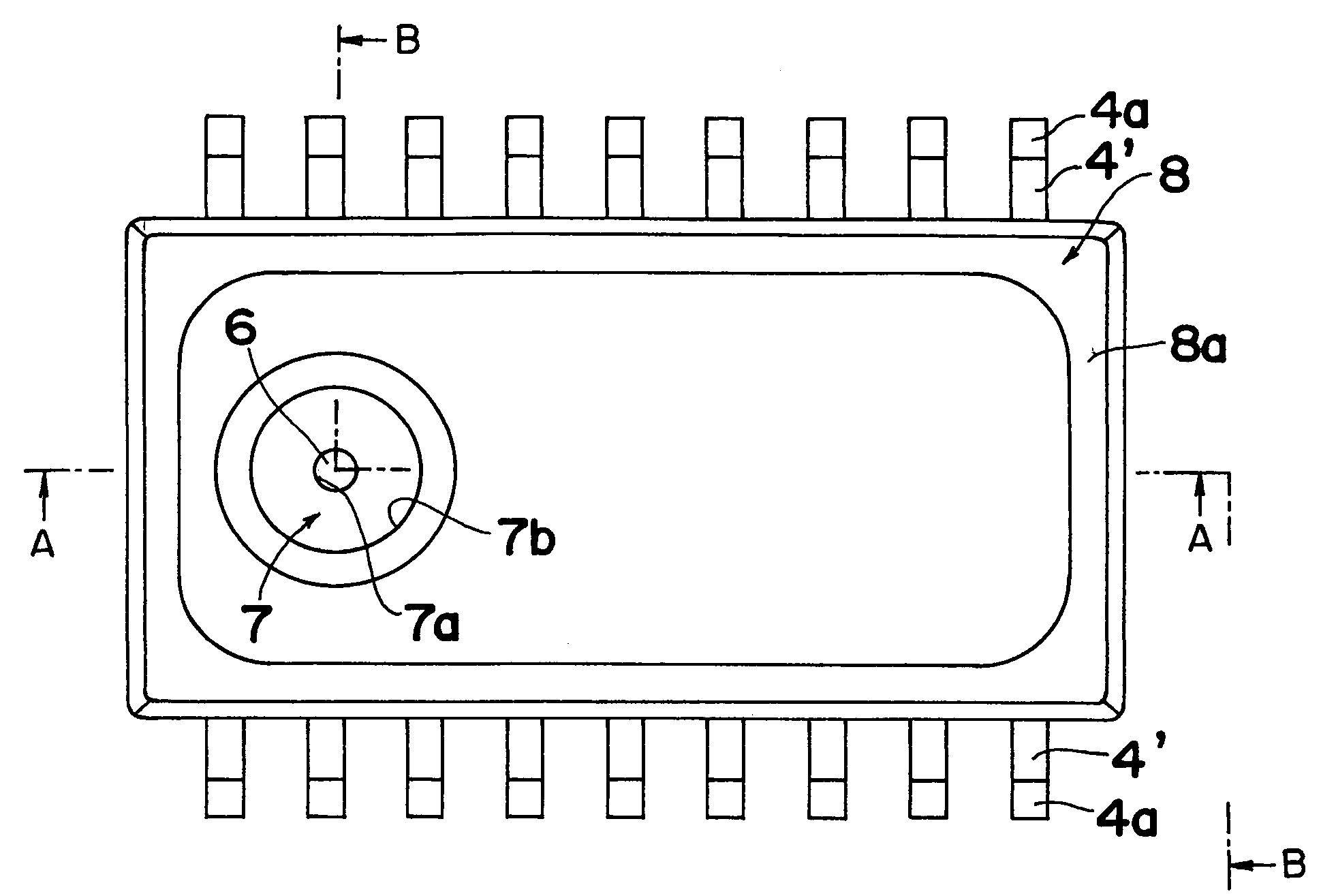
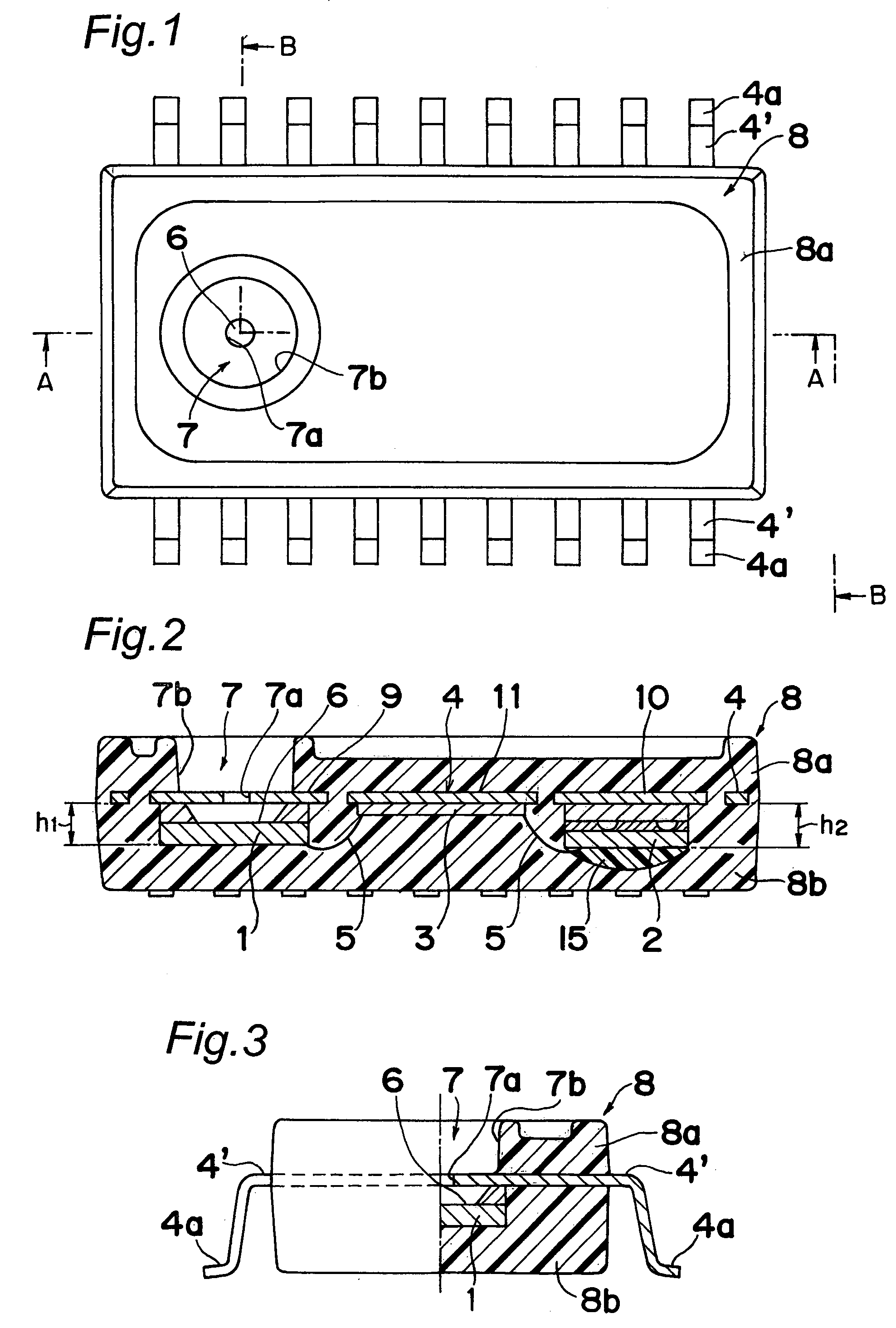
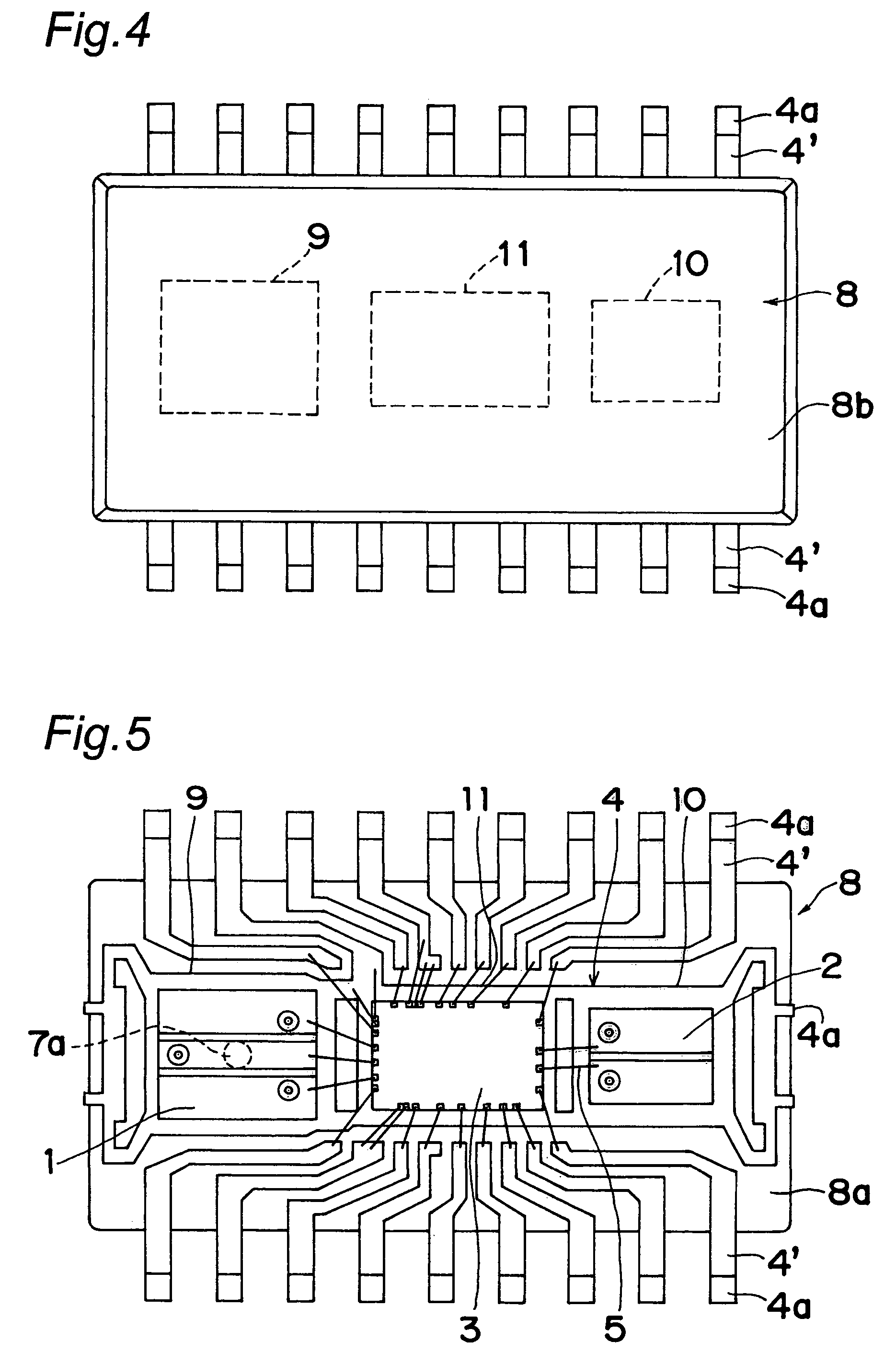
[0036]As shown in FIGS. 1 to 3, a sensor unit of the present invention may be used, for example, as a tire-air-pressure sensor. A sensor unit according to a first embodiment of the present invention includes a pressure sensor 1, an acceleration sensor 2 and a signal-processing circuit (signal processing IC) 3. The signal-processing circuit 3 is operable, only when the acceleration sensor 2 detects acceleration, to activate the pressure sensor 1. Each of the pressure sensor 1, the acceleration sensor 2 and the signal-processing circuit 3 is mounted on the bottom surface of a lead 4. The signal-processing circuit 3 is wire-bonded or electrically connected to each of the pressure sensor 1 and the acceleration sensor 2 through a plurality of bonding wires 5.

[0037]A portion of the lead 4 mounting the pressure sensor 1 is formed with one opening 7a for transmitting an external pressure to a pressure-receiving portion 6 formed in the pressure sensor 1. The pressure-receiving portion 6 is c...

second embodiment

[0042]With reference to FIGS. 6 to 8, a second embodiment of the present invention will be specifically described below. As shown in FIGS. 6 and 7, a sensor unit according to the second embodiment includes a pressure sensor 1, an acceleration sensor 2, and a signal-processing circuit (signal processing IC) 3 having a function designed to activate the pressure sensor 1 only when the acceleration sensor 2 detects acceleration. Each of the pressure sensor 1, the acceleration sensor 2 and the signal-processing circuit 3 is mounted on the bottom surface of a lead 4. The signal-processing circuit 3 is wire-bonded or electrically connected to each of the pressure sensor 1 and the acceleration sensor 2 through two bonding wires 5. A portion of the lead 4 mounting the pressure sensor 1 is formed with one opening 7a for transmitting an external pressure to a pressure-receiving portion 6 formed in the pressure sensor 1. The pressure-receiving portion 6 is composed, for example, of a diaphragm,...

third embodiment

[0048]With reference to FIG. 9, a third embodiment of the present invention will be specifically described below. As shown in FIG. 9, a sensor unit according to the third embodiment, each of a pressure sensor 1 and an acceleration sensor 2 has substantially the same height dimension or thickness. That is, the respective bottom surfaces of the pressure sensor 1 and the acceleration sensor 2 are located at substantially the same height position indicated by the dotted line L2. Further, an upper molded body 8a and a lower molded body 8b are formed such that the height dimension ta (thickness) between the top surface of the upper molded body 8a and the top surface of a lead 4 becomes substantially equal to the height dimension tb (thickness) between the bottom surface of the lower molded body 8b and each of the bottom surfaces of the pressure sensor 1 and the acceleration sensor 2. The remaining structures are the same as those in the second embodiment, and their description will be omi...


PUM

PropertyMeasurementUnit
pressureaaaaaaaaaa
height dimensionaaaaaaaaaa
flexibleaaaaaaaaaa

Abstract

A sensor unit includes a pressure sensor, an acceleration sensor and a signal-processing circuit, which are disposed on the bottom surface of a lead to form a line in the longitudinal direction of the sensor unit. The pressure sensor and the acceleration sensor are disposed at respective symmetrical positions with respect to the center of the signal-processing circuit in the longitudinal direction of the sensor unit. Each of the pressure sensor and the acceleration sensor has substantially the same height dimension. The sensors, the signal-processing circuit and the lead are sealed with a molded body, in such a manner as to allow lead terminals of the lead to protrude outside the molded body. The signal-processing circuit is operable, based on a signal from the acceleration sensor, to control the ON / OFF action of the pressure sensor.

Description

TECHNICAL FIELD[0001]The present invention relates to a sensor unit for measuring a plurality of physical quantities.BACKGROUND ART[0002]Heretofore, in a measuring system where it is required to measure a plurality of different types of physical quantities or a plurality of the same type of physical quantities different in detection range, a plurality of separately-packaged sensors have been used. In this case, the plurality of separately-packaged sensors have to be mounted on a circuit board individually. This involves the need for assuring a large space (area) for mounting these physical-quantity sensors in the circuit board, which leads to undesirable increases in size, complexity and cost of the measuring system.[0003]As one measure against this problem, it is conceivable to incorporate a plurality of sensors into a single package. For example, the following Patent Publication 1 discloses a compound sensor unit having a pressure sensor for detecting a pressure and a temperature ...

Claims


Application Information

Patent Timeline
Patent Type & Authority Patents(United States)
IPC IPC(8): G01D21/02G01D11/24G01L19/14G01P1/02B60C23/04G01L9/00G01L19/00
CPCB60C23/0408G01L19/0092G01L19/148G01L19/0084G01L19/141G01P1/023H01L2224/73265H01L2224/49171H01L2224/48091H01L2224/48247H01L2924/00014H01L2924/00H01L2924/181H01L2924/1815H01L2924/00012G01L19/14G01D21/02G01P1/02
Inventor ISHIGAMI, ATSUSHISAKAI, KOUJIMESHII, RYOSUKE
Owner MOSAID TECH
Why Eureka
Try Eureka