Generation of a Frame Synchronized Clock for a Wireless Video Receiver

a wireless video receiver and frame synchronization technology, applied in the direction of television systems, pulse automatic control, cathode-ray tube indicators, etc., can solve the problems of undesirable allocation of such bandwidth for these purposes, inapplicability of prior art solutions, and the amount of bandwidth that is required to send these signals, so as to preserve the use of bandwidth

Active Publication Date: 2008-03-06
AMIMON
View PDF10 Cites 14 Cited by
  • Summary
  • Abstract
  • Description
  • Claims
  • Application Information

AI Technical Summary

Benefits of technology

[0010]An apparatus for receiving essentially uncompressed HDTV video must generate an accurate pixel-rate clock to enable the reconstruction of a video frame. The clock pixel-rate generated must match a received video pixel-rate. In such system, signals for generation of horizontal and vertical synchronization are not transmitted over the wireless link to conserve the use of bandwidth. In the invention, a start of frame (SOF) indication is extracted by a symbol detection and synchronization (SDS) module and is used to generate the pixel-rate clock.

Problems solved by technology

However, the amount of bandwidth that is required to send these signals decreases the amount of bandwidth that is available for sending video data, i.e. significant portions of the available bandwidth are used to send such control signals.
In cases where the bandwidth is limited or better used for other purposes, for example, for the purpose of the transmission of video information and, in particular, in the case of the transmission of high-definition video information, the allocation of such bandwidth for these purposes is undesirable.
In wireless systems that do not have any frame buffering or have a minimal buffering, for example the apparatus described in the '459 application, the prior art solutions are not applicable.
Secondly, because there is no frame buffering a local oscillator cannot be used.
The video source on the transmit side jitters relative to the local oscillator of the receive side and no buffering is available to accommodate for such jitter.
Hence, in a wireless system having no frame buffering there is a challenge in generating the digital video output in a way that ensures that there are a predefined number of clocks between Hsync signals that are aligned with the video source.

Method used


Image

  • Generation of a Frame Synchronized Clock for a Wireless Video Receiver
  • Generation of a Frame Synchronized Clock for a Wireless Video Receiver
  • Generation of a Frame Synchronized Clock for a Wireless Video Receiver

Examples


Embodiment Construction

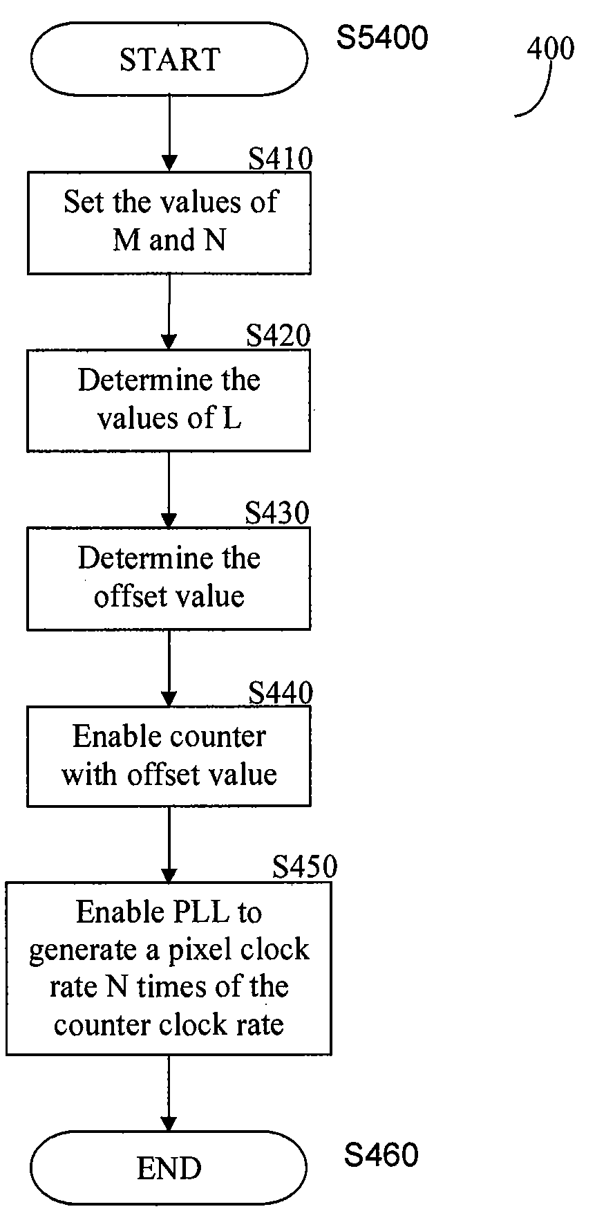
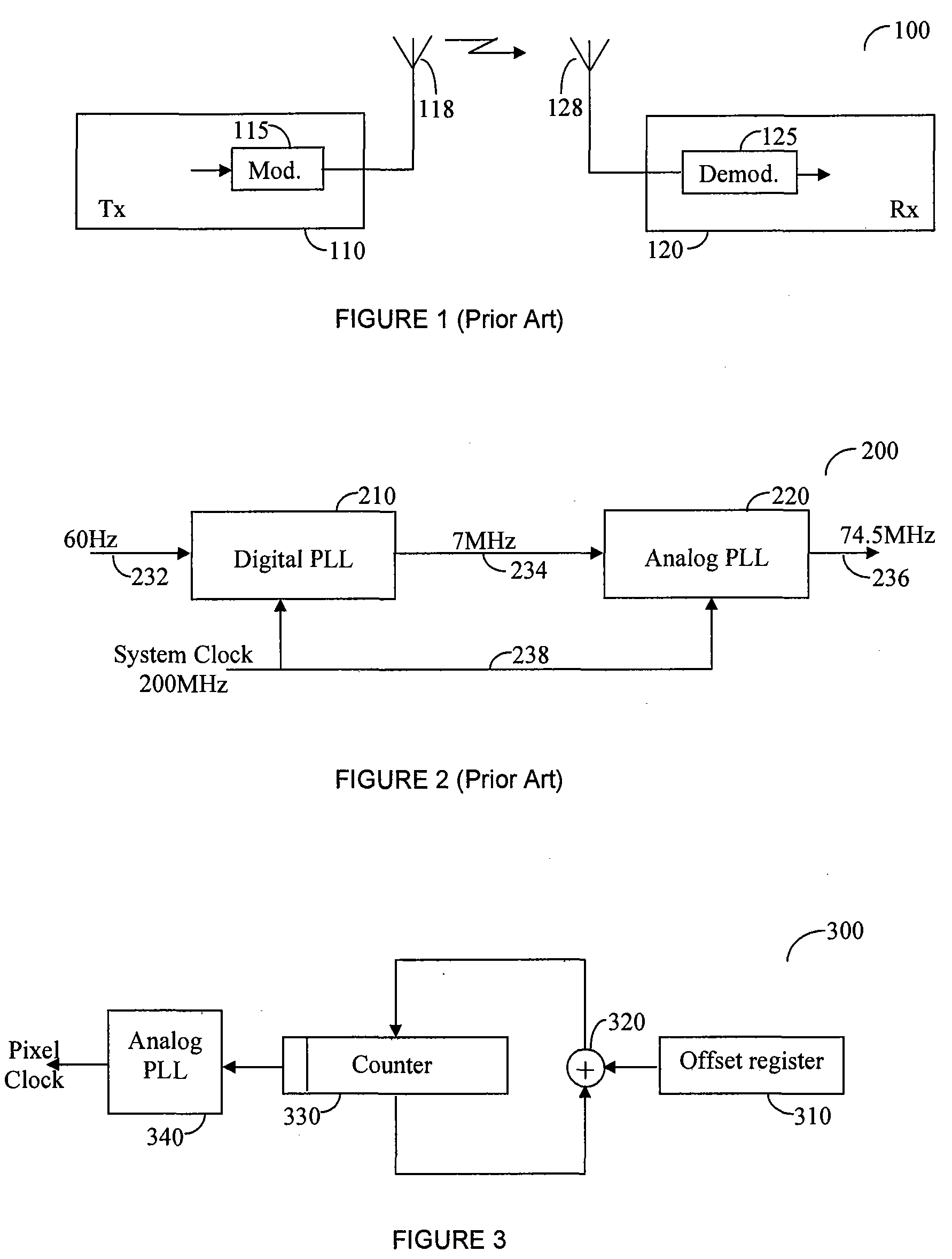
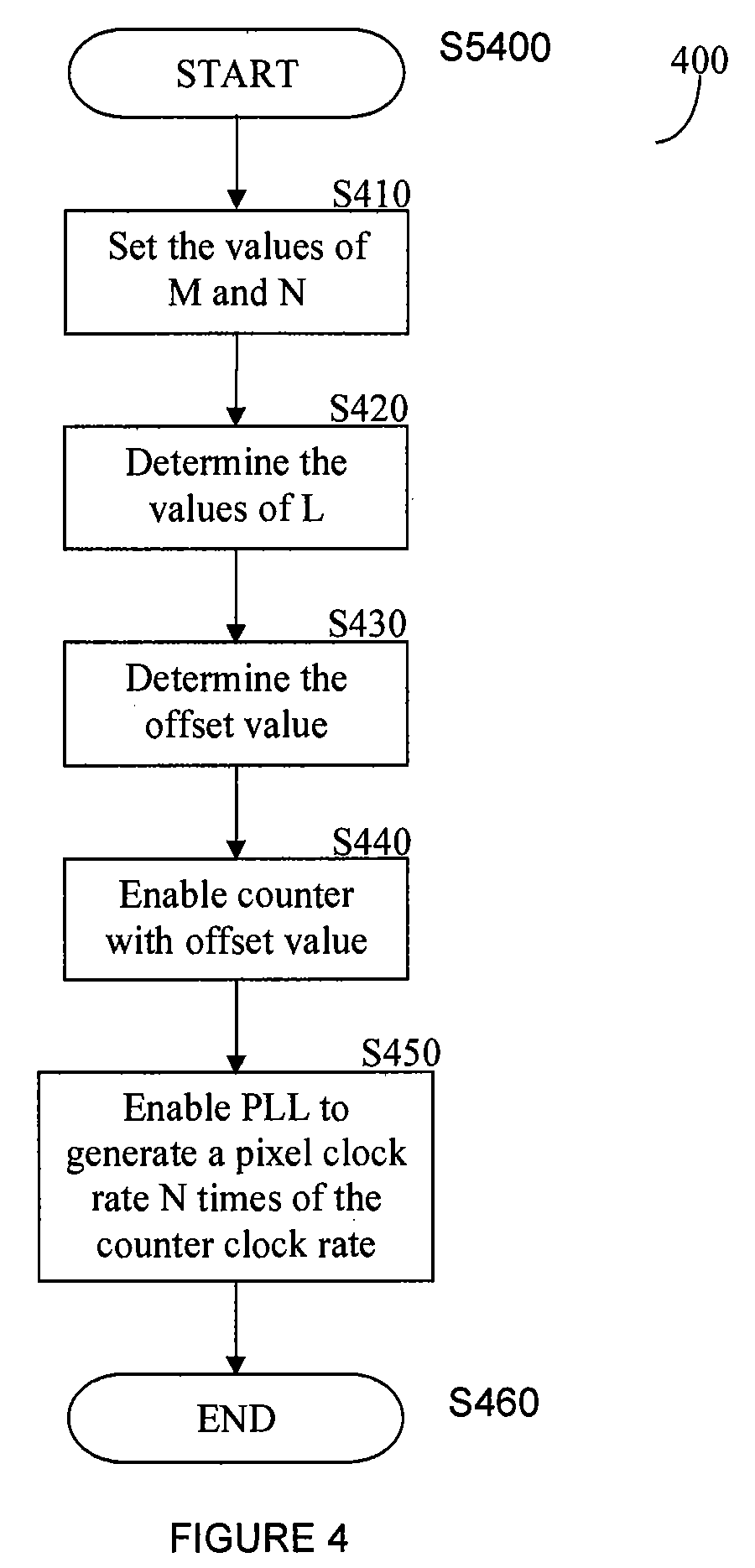
[0015]In an apparatus that receives an essentially uncompressed HDTV video there is a need to generate an accurate pixel-rate clock for reconstruction of the video frame. The clock that is generated must match the received video rate. To preserve bandwidth, signals for generation of horizontal and vertical synchronization are not transmitted over the wireless link. In accordance with the invention, the start of frame (SOF) indication that is extracted by a symbol detection and synchronization (SDS) module is used in the generation of the pixel clock. In accordance with the invention Hsync information which is transmitted to enable synchronization of the video signal. The invention uses signaling through the wireless link and reports to the receiver when Hsync occurs in the video source. The receiver then generates the video clock from the received signal using, for example, a phase-locked loop (PLL). In this way, the generated video clock adjusts itself in real-time relative to the ...


PUM


Abstract

An apparatus for receiving essentially uncompressed HDTV video must generate an accurate pixel-rate clock to enable the reconstruction of a video frame. The clock pixel-rate generated must match a received video pixel-rate. In such system, signals for generation of horizontal and vertical synchronization are not transmitted over the wireless link to conserve the use of bandwidth. In the invention, a start of frame (SOF) indication is extracted by a symbol detection and synchronization (SDS) module and is used to generate the pixel-rate clock.

Description

BACKGROUND OF THE INVENTION[0001]1. Field of the Invention[0002]The invention relates generally to the reception of uncompressed video over a wireless link. More specifically, the invention relates to the generation of a synchronization clock that is correlated to video frames received over a wireless link.[0003]2. Description of the Prior Art[0004]In common video reception systems, there are video control signals, such as the horizontal synchronization (Hsync) signal and the vertical synchronization (Vsync) signal. The Hsync and the Vsync signals may be used to generate a video pixel clock. Such signals may also be sent over the air for wireless transmission of video. However, the amount of bandwidth that is required to send these signals decreases the amount of bandwidth that is available for sending video data, i.e. significant portions of the available bandwidth are used to send such control signals.[0005]The video source is usually comprised of a video data signal, such as RGB ...

Claims


Application Information

Patent Timeline
Patent Type & Authority Applications(United States)
IPC IPC(8): H04N5/38H04N5/44
CPCH04N5/06H03L7/06H04N5/04G09G5/12
Inventor ELNATHAN, NATHANFREUNDLICH, SHAY
Owner AMIMON
Why Eureka
Try Eureka