
Supplied air respirator

a technology of air respirator and air supply, which is applied in the direction of life-saving devices, instruments, climate sustainability, etc., can solve the problems of limiting the information that the warning device can provide, the indication method of the warning device, and the prior art's inability to provide tactile responses

Pending Publication Date: 2021-07-29
RPB SAFETY
View PDF0 Cites 0 Cited by
  • Summary
  • Abstract
  • Description
  • Claims
  • Application Information

AI Technical Summary

Benefits of technology

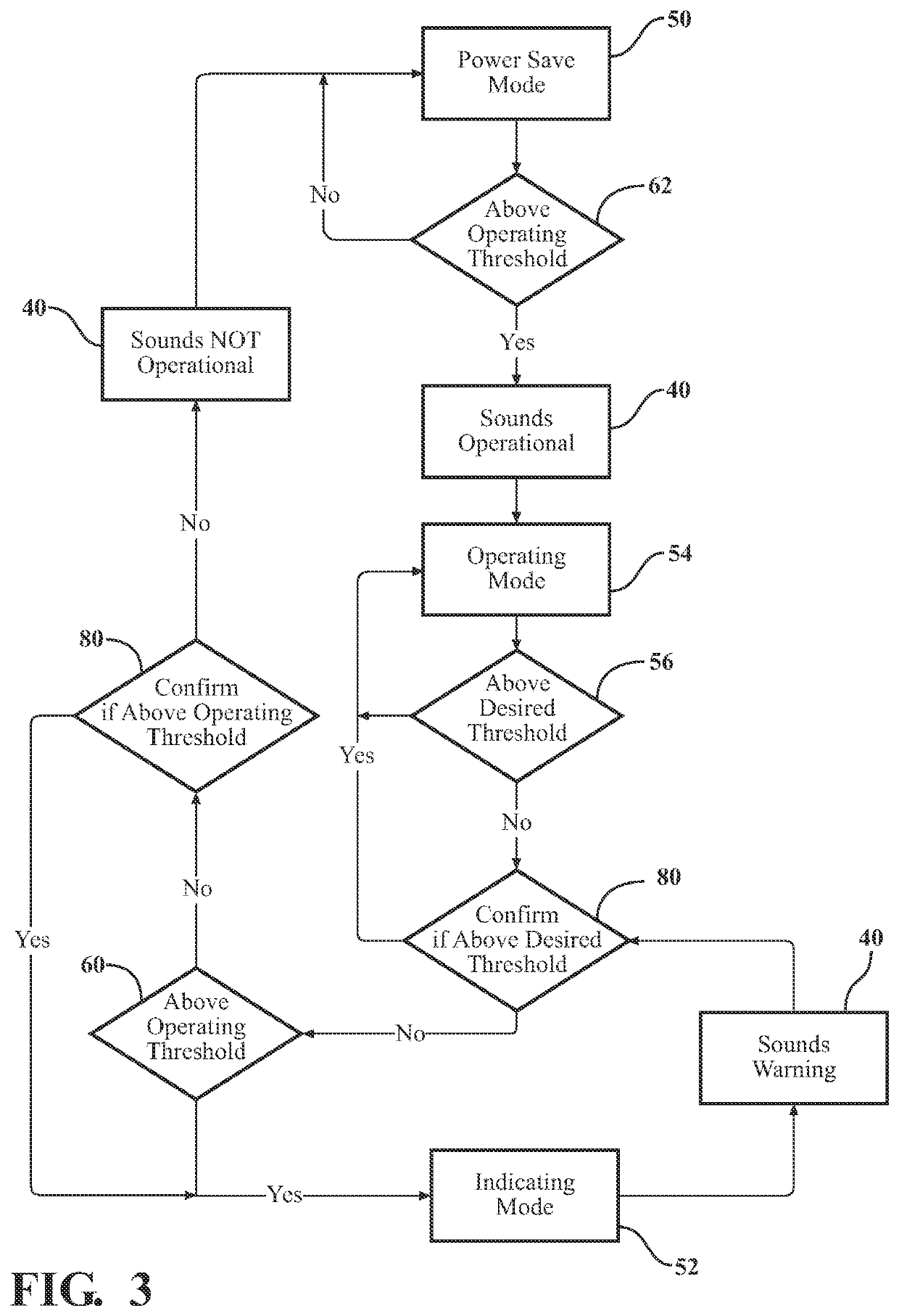
The present invention provides an air respirator with a warning device that can indicate when the air flow is below a recommended level. The device contains a differential pressure sensor, a CPU, and a vibration motor to alert the user. A barometric pressure sensor compensates for changes in atmospheric pressure. The warning device has two modes: operating mode and standby mode. In the operating mode, the device takes regular measurements and communicates with the user quickly, while in the standby mode, it conserves power and has longer periods between measurements. The device can transition to operating mode when a reading above the operating threshold is recorded.

Problems solved by technology

This limits both the indication method for the warning device and the information that the warning device can provide.
This is particularly true of supplied air respirators which typically do not have electric power.
Also, none of the prior art provides a tactile response which can be very important in highly noisy environments.

Method used


Image

  • Supplied air respirator
  • Supplied air respirator
  • Supplied air respirator

Examples


Embodiment Construction

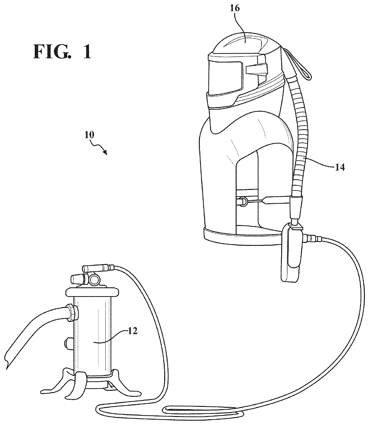
[0013]The supplied air respirator of the present invention is shown generally at 10. The respirator 10 includes a supplied air source 12, an air path or airflow tube 14 and a respirator headpiece 16. As will be appreciated by those of ordinary skill in the art, the supplied air source 12 provides pressurized air through the air path 14 to create positive pressure in the headpiece 16. It should be appreciated that the headpiece can take many different forms for example, a helmet, a visor or a hood.

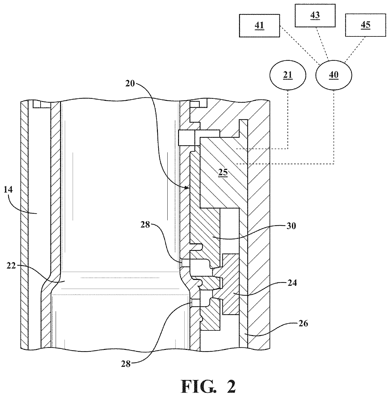
[0014]With reference to FIGS. 1 and 2, the respirator 10 has a control unit shown generally at 20 that provides a signal to the user of the operating modes of the respirator 10. The signal can be tactile, such as a vibration, auditory, such as a buzzer, or visual, such as a light or a combination of these.

[0015]The respirator 10 has this capability because the control unit 20 which acts as a warning device is electrically powered by a power source 21. In the disclosed embodiment, the power ...


PUM


Abstract

A supplied air respirator having an airflow path to supply supplied air to a user. The respirator includes a control unit having a sensor located in the airflow path that communicates with a CPU. The CPU also communicates with an indicator that can provide either tactile, audible or visual status indications. One or any combination of these can be used. A power source is provided for powering the CPU and the indicators. The. CPU compares a sensor signal from the sensor with a predetermined operating flow rate and a desired flow rate and indicates to the user the status of the respirator. The CPU continually communicates with said sensor and does not shut down.

Description

CROSS REFERENCE TO RELATED APPLICATION[0001]This application claims priority to U.S. Provisional Application No. 62 / 965,084 filed Jan. 23, 2020, which is incorporated herein by reference in its entirety.BACKGROUND OF THE INVENTION1. Field of the Invention[0002]The present invention relates to a supplied air respirator and more particularly to a supplied air respirator with a controller that signals various modes of operation of the supplied air respirator. The controller has an indicator that can signal a user when for example the respirator is operational, when the airflow is at a desired level for use, when the respirator is in standby mode and the battery life of the controller.2. Description of the Prior Art[0003]Warning devices for compressed air systems are generally known in the art for alerting the user when their flow rate is below a recommended level. The recommended level is often defined by the governing occupational health and safety agency. For example, the European st...

Claims


Application Information

Patent Timeline
IPC IPC(8): A62B9/00G06F1/3212A61M16/00
CPCA62B9/006A61M2016/0033A61M16/0003G06F1/3212G06F1/3287G06F1/325Y02D10/00A62B18/006
Inventor IVORY, GARTHHAMILL, WILLIAM C.WILLIAMS, EDWARD S.M.GERRARD, ALAN J.KELLY, SAMUEL M.
Owner RPB SAFETY
Learn More