Matrix converter

a matrix converter and converter technology, applied in the field of matrix converters, can solve the problems of increasing the cost associated with matrix converters, and achieve the effect of improving the thermal conditions of the generator, compact and efficient architectur

Active Publication Date: 2008-03-06
GENERAL ELECTRIC TECH GMBH
View PDF6 Cites 13 Cited by
  • Summary
  • Abstract
  • Description
  • Claims
  • Application Information

AI Technical Summary

Benefits of technology

[0041] A very compact and efficient architecture is possible if in particular the first stage of the converter is integrated into the stator of the generator. In order to additionally improve the th

Problems solved by technology

This in particular in combination with high phase order generators leads to excessive numbers o

Method used


Image

  • Matrix converter
  • Matrix converter
  • Matrix converter

Examples


Embodiment Construction

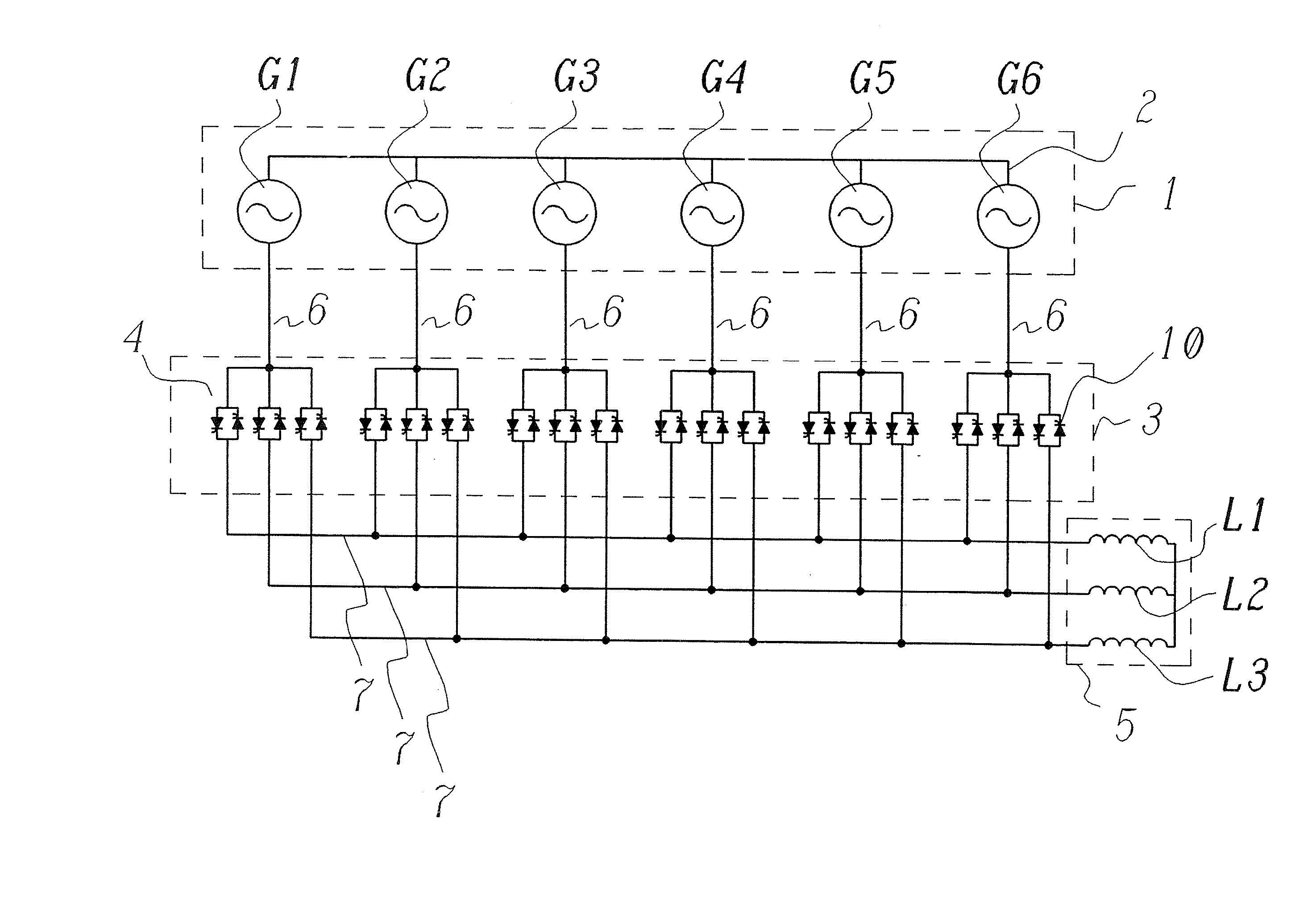
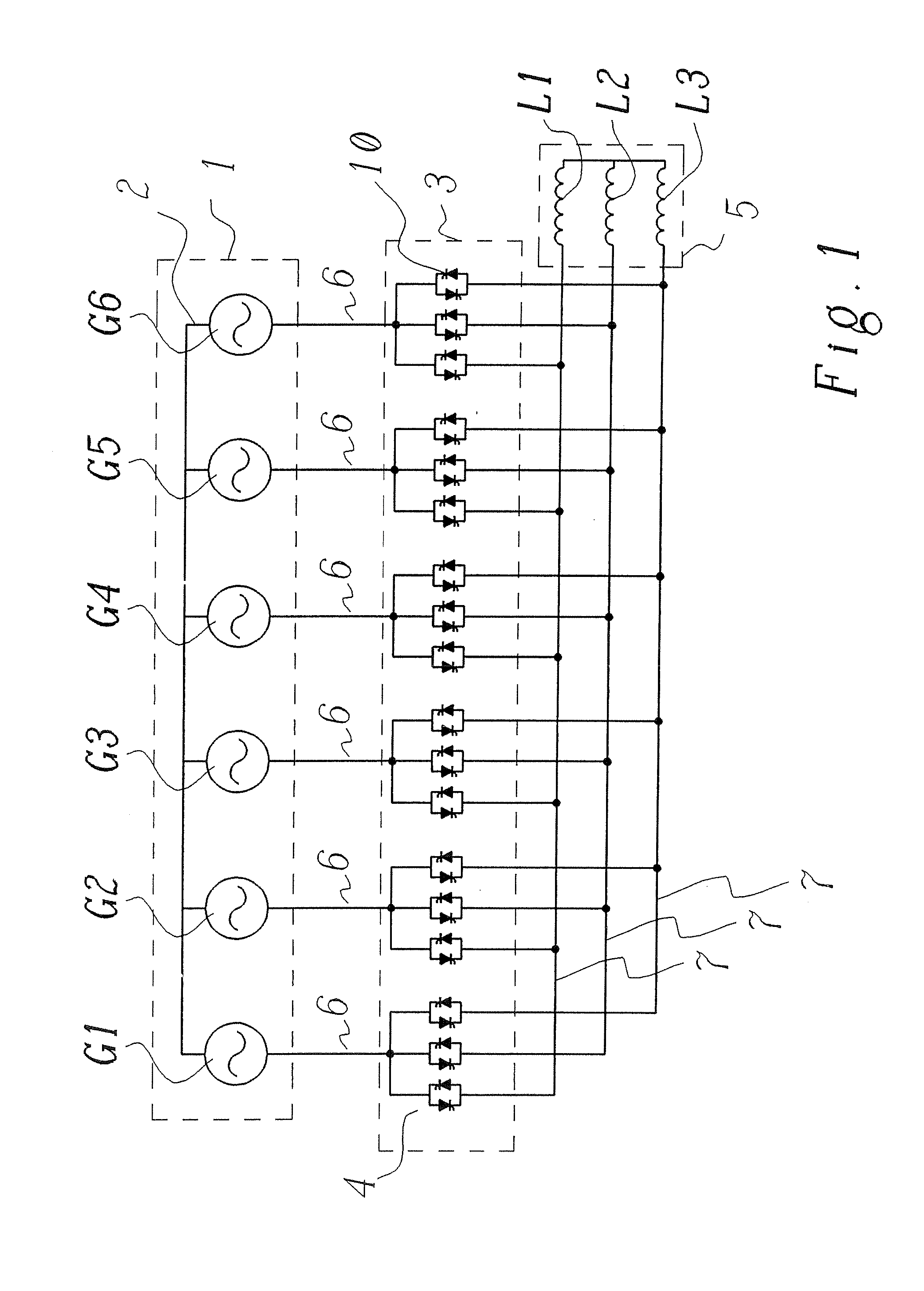
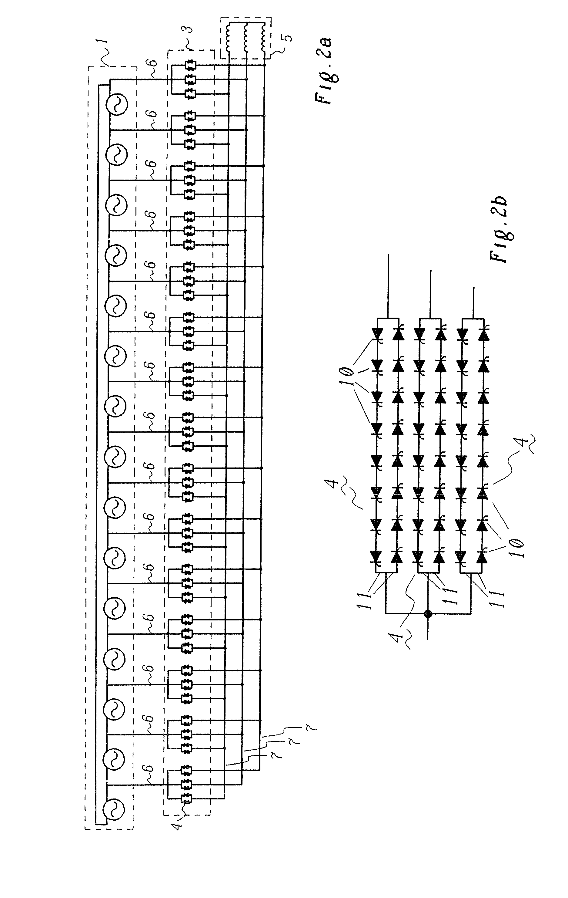
[0053] Referring to the drawings, which are for the purpose of illustrating the present preferred embodiments of the invention and not at all for the purpose of limiting the same, FIG. 1 shows a generator set-up, in which a generator 1 with six generator phases G1 to G6, which are star connected (reference numeral 2), is connected to a matrix converter 3. A polyphase alternating current 6 comprising six phases (m=6) therefore gives the input of the matrix converter 3. Each of these phases is individually connected via a bidirectional switch 4 to any of the three alternating output current phases 7. This arrangement of the bidirectional switches 4 leads to a 6×3 matrix of switches, or more generally, for m phases of the polyphase alternating current 6 and for n phases of the alternating output current 7, the matrix converter comprises an m×n matrix of bidirectional switches 4. By means of corresponding controls it is therefore possible to, at any time, connect any input phase with an...


PUM


Abstract

A matrix converter for converting a polyphase alternating current into a desired alternating output current includes at least two stages; a plurality of controllable bidirectional switches, converts m phases of the polyphase alternating current into alternating output current with n (n<m) phases of a load; and a controllable bidirectional switch controlling each phase of the polyphase alternating current in at least one stage of the converter.

Description

[0001] This application is a continuation of International Patent Application No. PCT / EP2006 / 060617, filed on Mar. 10, 2006, which claims priority to Swiss Patent Application No. CH 00587 / 05, filed on Mar. 31, 2005. The entire disclosure of both applications is incorporated by reference herein.[0002] The present invention relates to the field of high phase order generator equipment with power electronics. The present invention in particular relates to a matrix converter for the conversion of electrical power, which is typically connected to a generator for conversion of generated polyphase alternating current from the generator into a polyphase alternating current adapted to the grid. BACKGROUND [0003] In power generation, at a specified output, an increase of the rotary speed of a turbine is associated with a decrease in size and costs. Efficiency, too, can be improved. So far, power generation turbines up to 70 MW are connected to generators by way of gearing arrangements, so as t...

Claims


Application Information

Patent Timeline
IPC IPC(8): H02M5/06
CPCH02M5/271
Inventor LACAZE, ALAIN
Owner GENERAL ELECTRIC TECH GMBH
Why Eureka
Try Eureka