
Power Module

a power module and power supply technology, applied in the direction of fixed capacitor details, printed circuit non-printed electric components association, semiconductor/solid-state device details, etc., can solve the problems of large surge voltage and electromagnetic interference (emi) noise between drain and source terminals of power devices, and the thermal condition of the snubber capacitor is improved, and the smoothing effect of voltage surge is enhanced

Pending Publication Date: 2022-06-23
ZF FRIEDRICHSHAFEN AG
View PDF0 Cites 0 Cited by
  • Summary
  • Abstract
  • Description
  • Claims
  • Application Information

AI Technical Summary

Benefits of technology

The power module described in this patent improves the thermal condition of the snubber capacitor and enhances the smoothing effect. It includes a first conductive layer, a second conductive layer, at least one power semiconductor element between the two layers, first and second cooling members, and a snubber capacitor. The snubber capacitor has multiple layers including conductive transition layers that help to smooth voltage surge and prevent overheating. The design helps to keep the snubber capacitor well fixed and reduces uneven distribution of stress. Overall, the power module provides efficient and reliable electrical power conversion.

Problems solved by technology

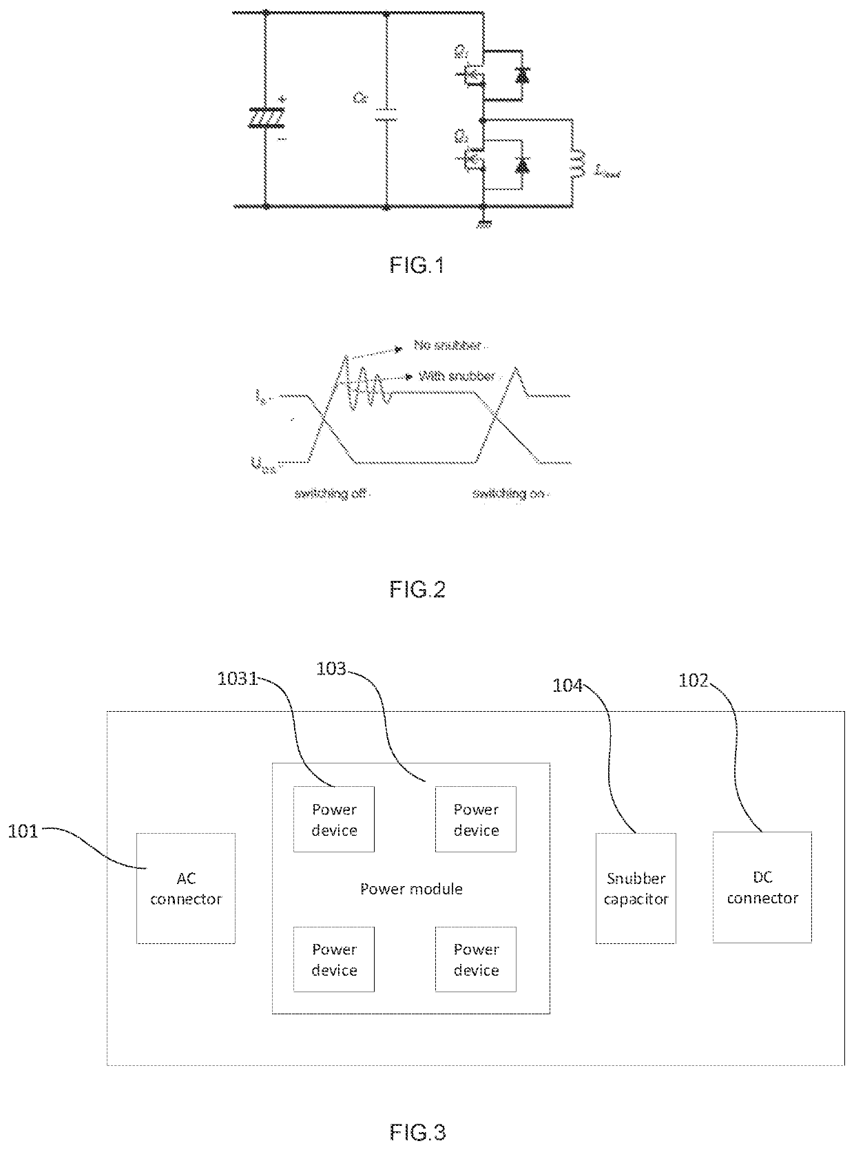
In addition, the power devices are usually coupled with stray inductance of a power module package and surrounding circuits, and fast switching capability of the power devices causes a high instantaneous rate of change in voltage over time (dv / dt), which results in large surge voltage and Electromagnetic Interference (EMI) noise between drain and source terminals of the power devices when switching off.
In the traditional inverter, the snubber capacitor is only provided adjacent to part of the power devices, thus the smoothing effect of the snubber capacitor has been limited.
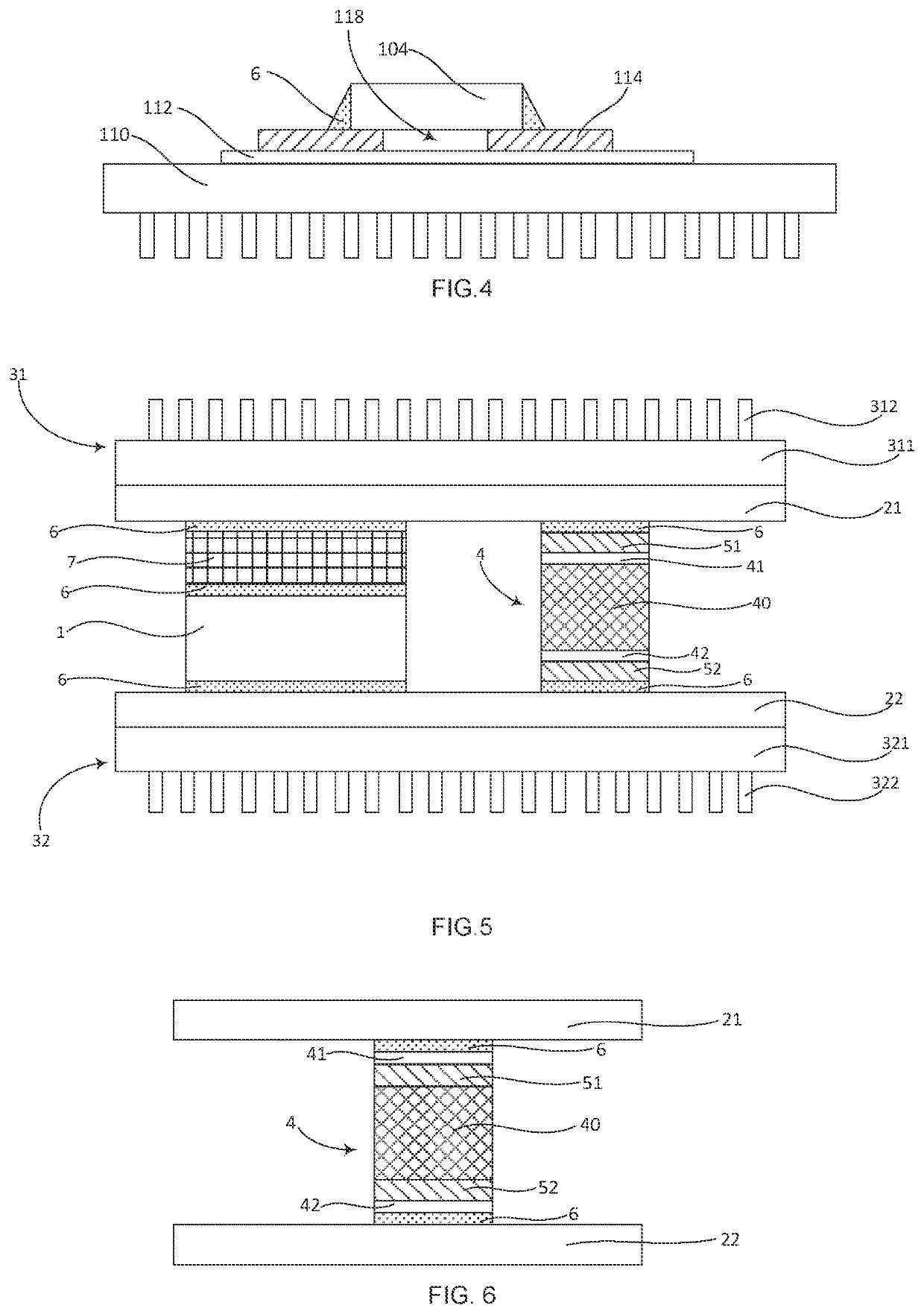
In this design, the heat generated by the MLCC 104 is only dissipated through the solder material 6 which results in an undesirable heat conduction efficiency.
In some cases, the snubber capacitors are even burnt under bad thermal conditions.

Method used


Image

  • Power Module
  • Power Module
  • Power Module

Examples


Embodiment Construction

[0041]Reference will now be made to embodiments of the invention, one or more examples of which are shown in the drawings. Each embodiment is provided by way of explanation of the invention, and not as a limitation of the invention. For example, features illustrated or described as part of one embodiment can be combined with another embodiment to yield still another embodiment. It is intended that the present invention include these and other modifications and variations to the embodiments described herein.

[0042]Referring now to the drawings, embodiments of the invention are described in detailed. In this invention, the power modules of different embodiments are mainly used in the automotive industry where, unlike in PCB application, the operation conditions of power modules are much stricter. For example, in the automotive industry, the operating temperature of the power modules is −40° C.˜150° C., the voltage between the first conductive layer and the second conductive layer is 30...


PUM

PropertyMeasurementUnit
operating temperatureaaaaaaaaaa
voltageaaaaaaaaaa

Abstract

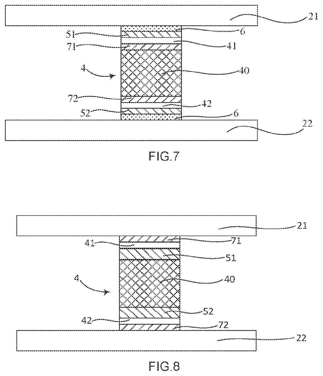
A power module includes at least one power semiconductor element between first and second conductive layers, a first cooling member on the first conductive layer, a second cooling member under the second conductive layer, and at least one snubber capacitor between the first and second conductive layers. Each snubber capacitor has a capacitor core between first and second electrodes and first and second transition layers. The first transition layer is between the first conductive layer and the first electrode and the second transition layer is between the second electrode and the second conductive layer, or the first transition layer is between the first electrode and the capacitor core and the second transition layer is between the capacitor core and the second electrode. The first and second transition layers are conductive. A thermal expansion coefficient of the transition layers is between thermal expansion coefficients of adjacent elements of the snubber capacitor.

Description

CROSS-REFERENCE TO RELATED APPLICATION[0001]The present application is related and has right of priority to German Patent Application No. 10 2020 216 476.2 filed on Dec. 22, 2020, the entirety of which is incorporated by reference for all purposes.FIELD OF THE INVENTION[0002]The invention relates generally to a power module, in particularly a power module with inner snubber capacitors.BACKGROUND OF THE INVENTION[0003]Power devices (wide bandgap (WBG) semiconductors, such as Silicon Carbide (SiC), Gallium Nitride (GaN)) are becoming more and more popular in applications where fast and efficient switching is required, such as power supply applications. In addition, the power devices are usually coupled with stray inductance of a power module package and surrounding circuits, and fast switching capability of the power devices causes a high instantaneous rate of change in voltage over time (dv / dt), which results in large surge voltage and Electromagnetic Interference (EMI) noise between...

Claims


Application Information

Patent Timeline
Patent Type & Authority Applications(United States)
IPC IPC(8): H05K7/20H05K1/18H05K1/02
CPCH05K7/209H05K1/181H05K2201/068H05K2201/10015H05K2201/10166H05K1/0271H01L25/16H01L23/3672H01G4/232H01G4/2325H01G4/30H01G4/008H01G4/0085H01L23/36H01L25/072H01L23/50
Inventor LIU, WEI
Owner ZF FRIEDRICHSHAFEN AG
Learn More