Optical pickup

a pickup and optical technology, applied in the field of optical pickups, can solve the problems of short working distance of the objective lens for a bd, inability to make the infrared laser or the red laser converge appropriately, and inability to accurately record or reproduce a bd medium. the effect of improving the recording accuracy

Inactive Publication Date: 2008-03-06
FUNAI ELECTRIC CO LTD
View PDF4 Cites 7 Cited by
  • Summary
  • Abstract
  • Description
  • Claims
  • Application Information

AI Technical Summary

Benefits of technology

[0015]An object of the present invention is to provide an optical pickup that includes objective lenses having two different numerical apertures and can improve accuracy of recording and reproducing a plurality of optical disc medium such as a CD medium, a DVD medium and a BD medium, even if an error occurs in the objective lens and the objective lens holder in the manufacturing and / or assembling process.

Problems solved by technology

On the other hand, the objective lens for a CD and a DVD cannot converge the blue laser sufficiently because its NA is small, so it cannot record or reproduce a BD medium correctly.
Further, if the objective lens for a BD is used, it cannot make the infrared laser or the red laser converge appropriately.
However, in the conventional optical pickup having two objective lenses as described above, the working distance of the objective lens for a BD is short.
If the objective lens and / or the objective lens holder contact with the optical disc medium, the optical pickup or the optical disc medium may be damaged and cause a malfunction.
In addition, if there is a mismatching state of the tilt angle between the two objective lenses, coma aberration occurs so that performance of the optical pickup is lowered.
Then, the objective lens and / or the objective lens holder may contact with the optical disc medium, which may cause a malfunction or damage to the optical pickup and / or the optical disc medium.

Method used


Image

  • Optical pickup
  • Optical pickup
  • Optical pickup

Examples


Embodiment Construction

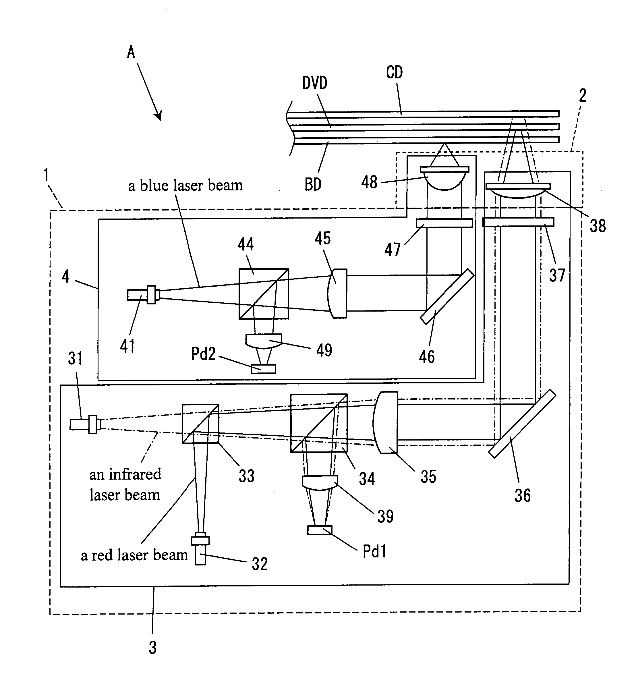
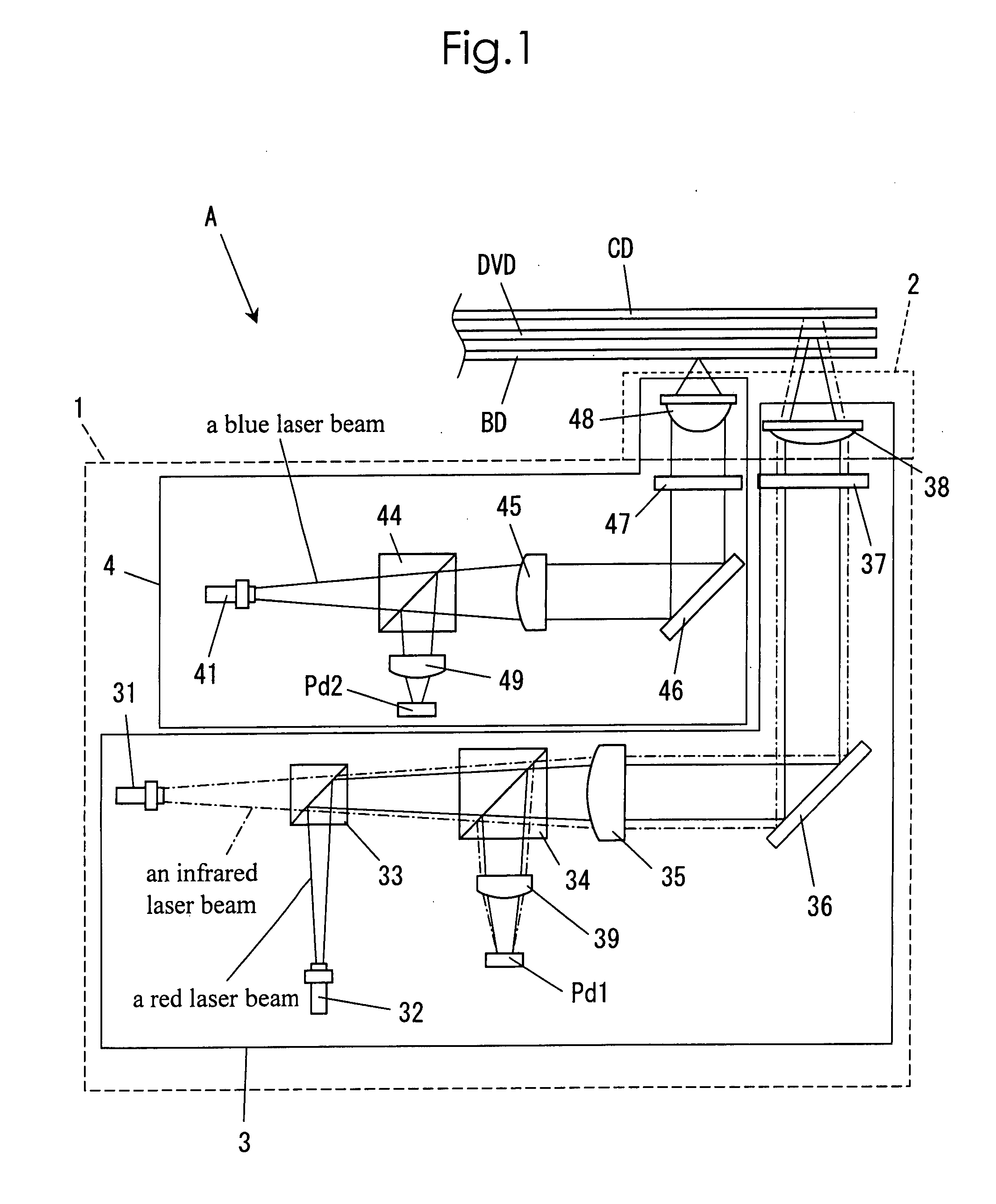
[0036]Hereinafter, an embodiment of the present invention will be described with the attached drawings. FIG. 1 is a layout diagram showing a structure of an example of an optical pickup according to the present invention. An optical pickup A shown in FIG. 1 includes a main body 1 and an actuator 2 that drives an objective lens. The optical pickup A shown in FIG. 1 includes a first optical system 3 for recording and reproducing a CD medium or a DVD medium and a second optical system 4 for recording and reproducing a BD medium. As to the optical pickup shown in FIG. 1, an optical path of an infrared laser is shown by a dashed dotted line, and an optical path of a red laser is shown by a solid line for convenience sake. In addition, an optical path of a blue laser is also shown by a solid line. Here, the CD medium includes a CD-ROM medium, a CD-R medium, a CD-RW medium and the like, and the DVD medium includes a DVD-ROM medium, a DVD-R medium, a DVD+R medium, a DVD-RW medium, a DVD+RW ...


PUM

PropertyMeasurementUnit
wavelengthaaaaaaaaaa

Abstract

An optical pickup includes a first objective lens, a second objective lens having a numerical aperture different from that of the first objective lens, and an objective lens holder. The first objective lens is attached to the objective lens holder via a spacer that has a cylindrical shape and is provided with a lens receiving portion of a stepped shape for receiving the first objective lens, a protruding portion having cushioning properties that protrudes from the upper surface, and a salient portion having a spherical shape formed at the lower surface. The protruding portion is formed so that a tip thereof is closer to an optical disc medium than any other part of the objective lens holder.

Description

[0001]This application is based on Japanese Patent Application No. 2006-233565 filed on Aug. 30, 2006, the contents of which are hereby incorporated by reference.BACKGROUND OF THE INVENTION[0002]1. Field of the Invention[0003]The present invention relates to an optical pickup that projects a laser beam to an optical disc for reproducing or recording data, in particular an optical pickup including lenses having different numerical apertures for recording or reproducing a CD medium, a DVD medium and a BD medium.[0004]2. Description of Related Art[0005]An optical disc apparatus performs recording or reproducing of data by projecting a laser beam from an optical pickup to an optical disc that is a recording medium. If the optical disc apparatus can reproduce a CD (Compact Disc) medium and a DVD (Digital Versatile Disc) medium, the optical pickup is equipped with a laser light source that emits an infrared laser for a CD (approximately 780 nm) and a red laser for a DVD (approximately 650...

Claims


Application Information

Patent Timeline
Patent Type & Authority Applications(United States)
IPC IPC(8): G11B7/135G11B7/00
CPCG11B7/082G11B7/0935G11B2007/0006G11B7/1374G11B7/22G11B7/1201G11B7/121
Inventor HATANO, SHINYA
Owner FUNAI ELECTRIC CO LTD
Why Eureka
Try Eureka